 Nix McRetro
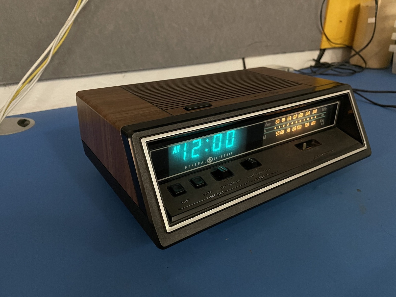
All good things eventually come to an end. You’re probably here because you have watched all four videos in the series so far. This is the fifth and final video on this alarm clock radio. Below are the capacitor values needed and their locations on the board.
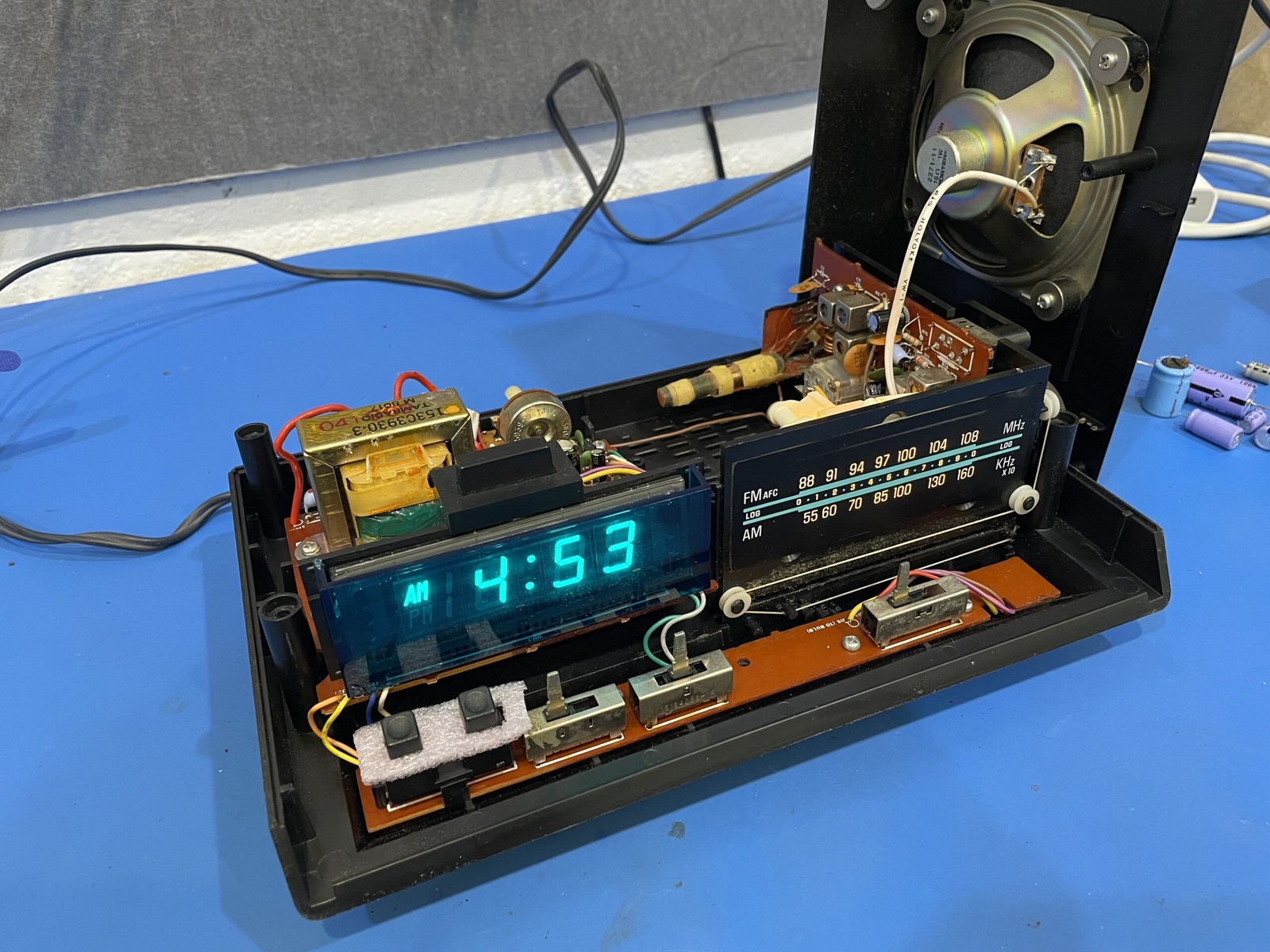
I’m not sure if this is an A or B revision because the stickers were missing. You can find a write up and some more information at the Radio Museum.
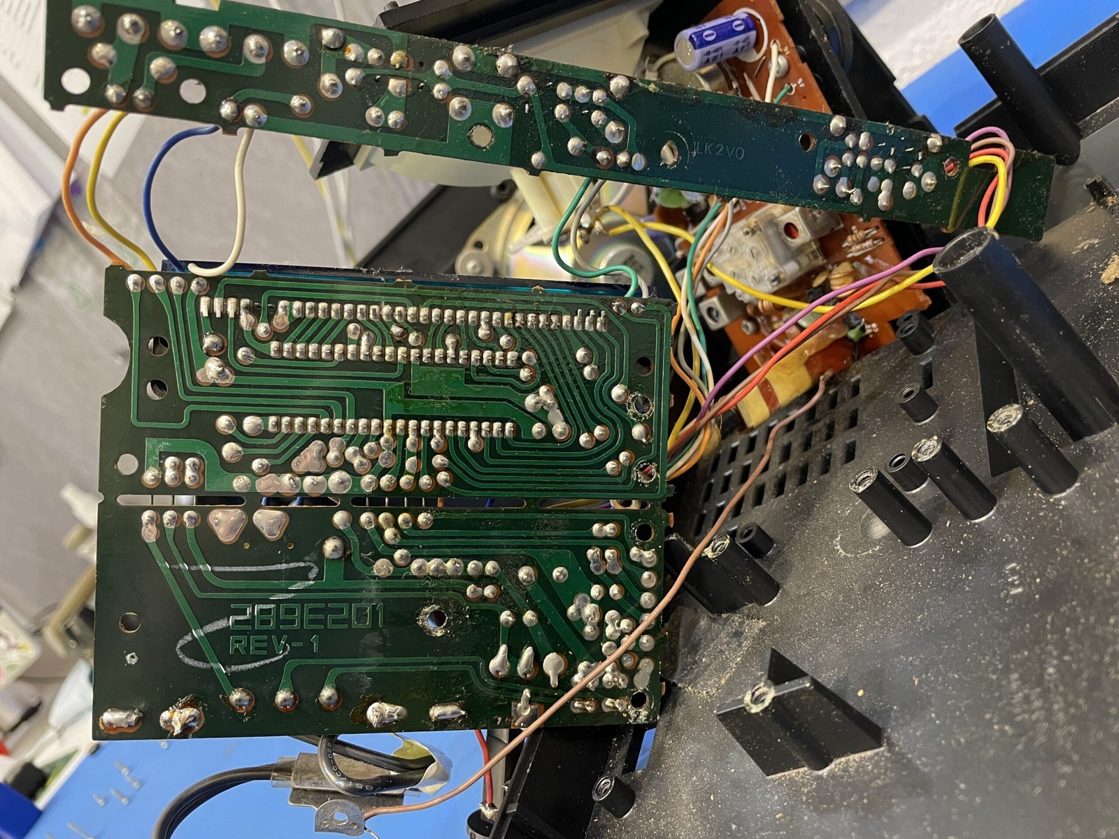
Note that all capacitor markings are underneath capacitors. On this unit the sticker with model number missing from base. If any of your switches need cleaning some plastic safe contact cleaner is the way to go.
You can either download the PDF version or copy and paste out the following to a plain text file.
-----------------------------------------------------------------
POWER CIRCUIT
-----------------------------------------------------------------
Marking	Value	Voltage	Width	Height	E14	Notes
Axial	1000uF	35V	16mm	32mm	1600791	Upgraded to 50V
C34	1000uF	16V	15mm	25mm	1219471	Upgraded to 25V
C207	100uF	35V	21mm	10mm	3254079	Same specifications
C205	22uF	35V	8mm	13mm	1848399	Upgraded to 50V
-----------------------------------------------------------------
RADIO BOARD
-----------------------------------------------------------------
Marking	Value	Voltage	Width	Height	E14	Notes
C21	220uF	6.3V	8mm	12mm	2217563	Upgraded to 25V
C27	100uF	10V	8mm	12mm	3254079	Upgraded to 35V
C28	100uF	10V	8mm	12mm	3254079	Upgraded to 35V
C29	470uF	16V	10mm	20mm	3254036	Same specifications
-----------------------------------------------------------------