 Nix McRetro
Electrolytic capacitors can deteriorate with age, heat and use, and these Aiwas have plenty of ageing capacitors to investigate. Here we have a great example, recapping an Aiwa Mega-CD boom box. Not the Sega Mega Drive part, just the Aiwa boom box part in this four-part series of videos.
The board is absolutely covered in capacitors, which is probably not surprising for an audio system. I’ve got the replacements ready, mostly Panasonic and Rubycon parts, and it’s time to bring out the mighty Hakko 808 desoldering gun. I do love this thing, even if I need a transformer to run it here in Australia.
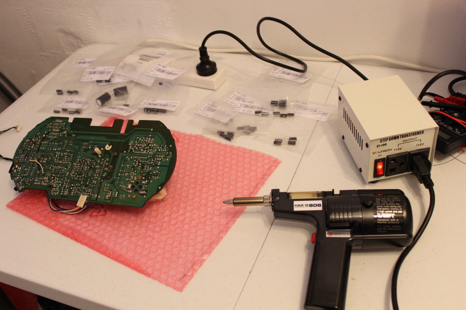
Rather than removing everything at once, I’ve been working through the board a little at a time. Take out a capacitor, check the value and orientation, install the replacement and move on. That way there’s rather less chance of forgetting what was where. Which is always a good thing!
The larger components went fairly smoothly, including the 470 uF and 3300 uF capacitors. Some of the originals were held down with glue, which made removing them considerably less enjoyable. After those were out of the way, I still had a lovely collection of smaller capacitors to deal with.
Getting close to the board also revealed something I hadn’t noticed earlier. There was a very fine crack running through part of the PCB near one of the capacitor positions. I could see it from both sides, which made me wonder whether some of the tracks might have been damaged as well. That’s something I’ll need to investigate with the multimeter.
One of the old capacitors also left behind an unpleasant amount of residue. Thankfully, most of it was around the component legs, although some had reached the board. A little cleaning with isopropyl alcohol helped tidy things up before fitting the replacement.
There were plenty more capacitors to change after that. I also replaced the 7806 voltage regulator while I had the board on the bench. With any luck, that might help with some of the power problems this Aiwa has been having.
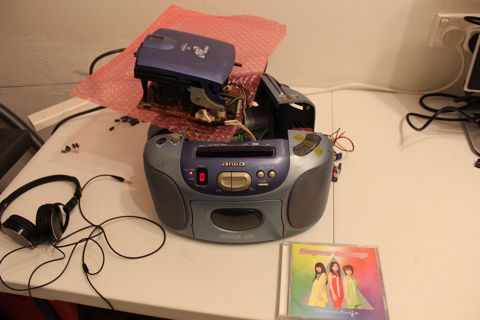
Once everything had been soldered in, I trimmed the excess leads and inspected the underside of the board. The joints were looking reasonably tidy, although I did find a few capacitors that could use straightening. It’s quite satisfying seeing the board with all those shiny new components in place.
This particular recording stops at the end of the capacitor replacement. I hadn’t powered everything up for a proper test yet, so we’ll find out whether the work made a difference in the next instalment.
And for the most part, I think we can label this one as a partial win? I mean we got the CD drive LED to light up? On to the next part, Volume check!
Sources
Related Posts