 Nix McRetro
The above video is not the one I originally intended, however YouTube screwed up the upload. Then I accidentally deleted the video and attempted to recover it… it was gone. Nevermind, enjoy some transformer rantings.
Started off the weekend by joining the two blue (blue->blue) and two white (white->white) as they were separate for reasons unknown. They both feed into the board and supply voltage from the known working transformer, so they both needed to be connected - possibly on different rails?
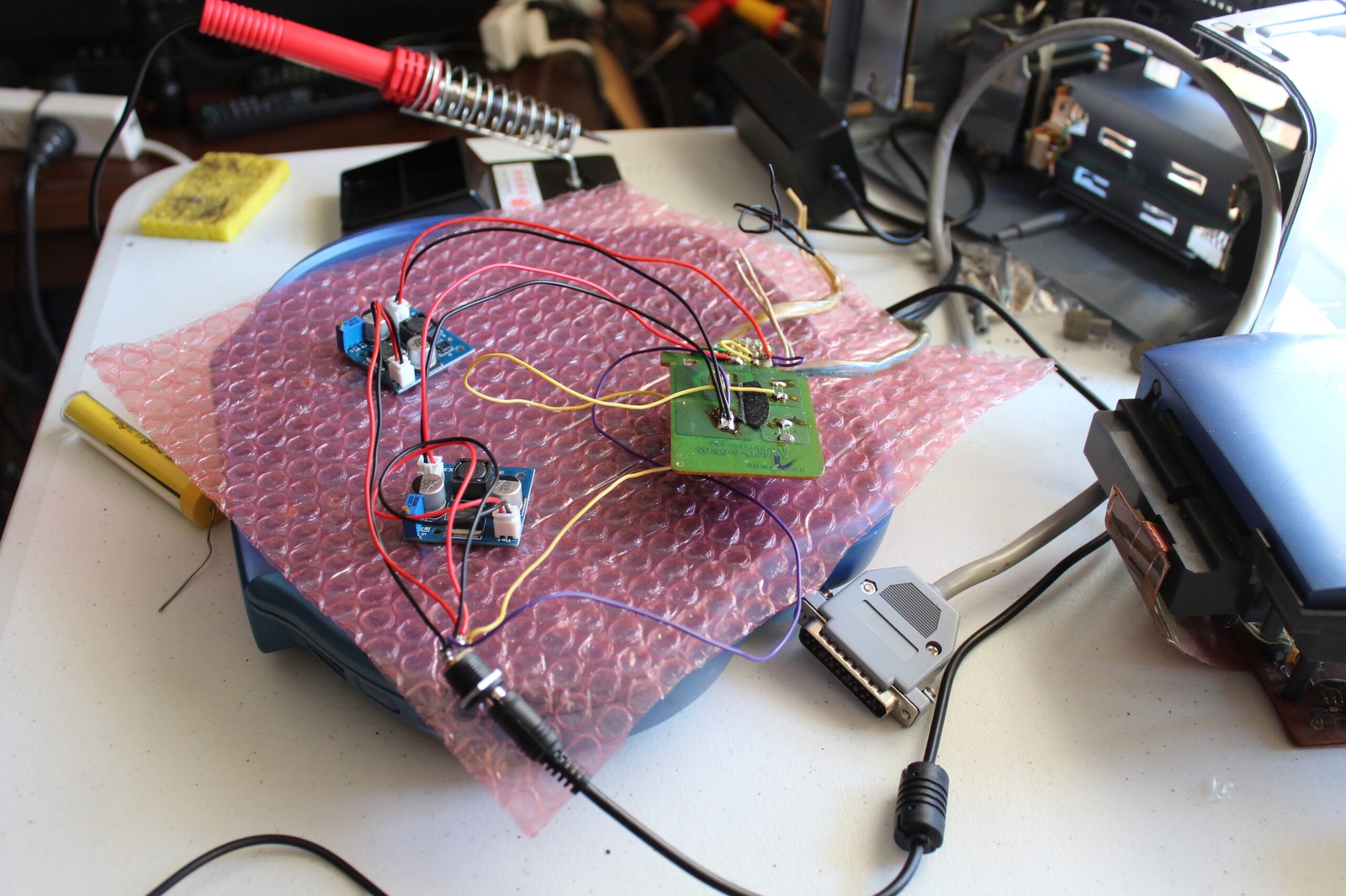
Next up we have the DC-DC stepdown converters attached. One is tuned to 6.3V, the other 9.75V. Ground is wired up to the same point on the battery PCB that feeds off into the black transformer in the background via the socket.
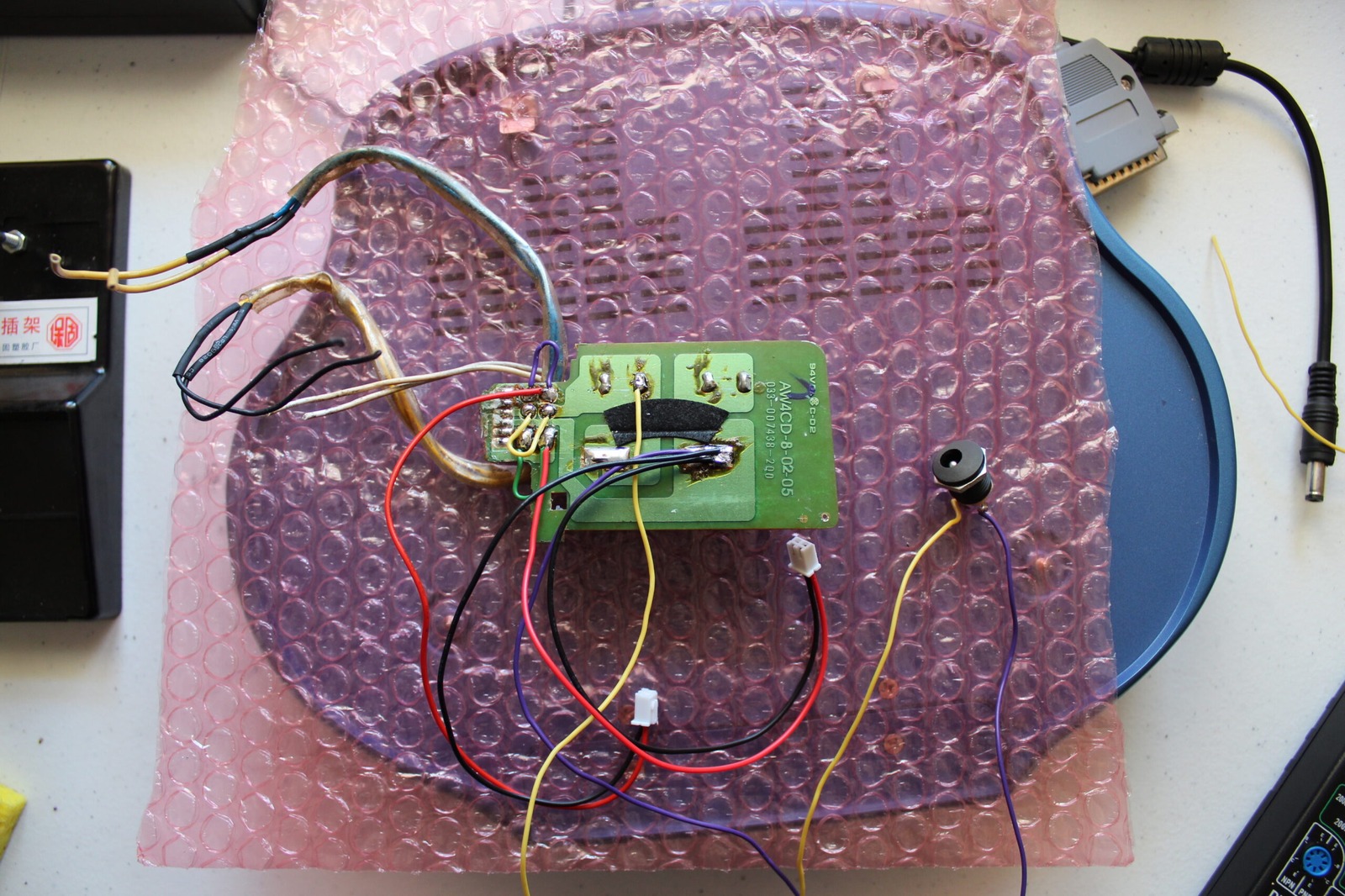
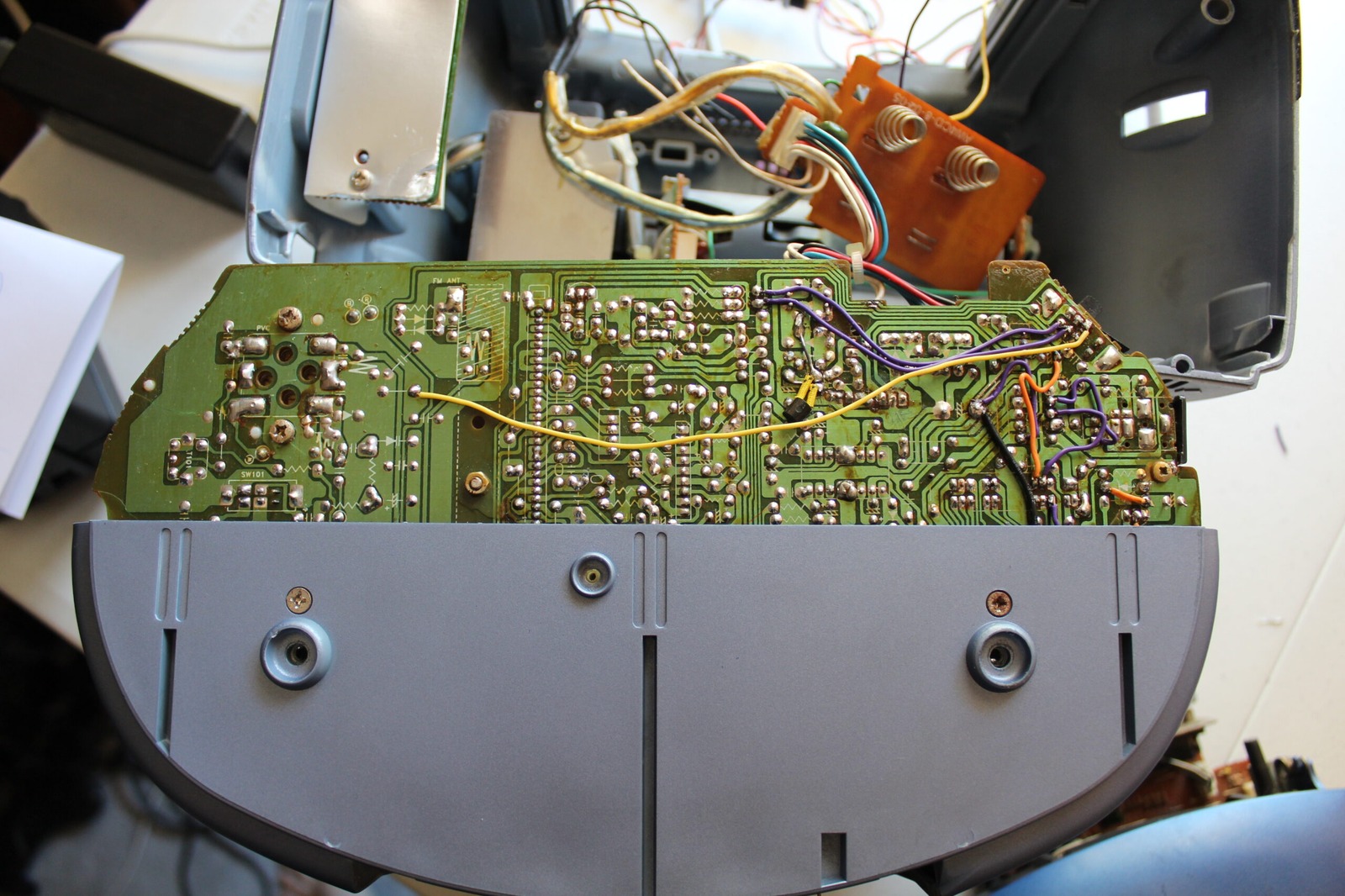
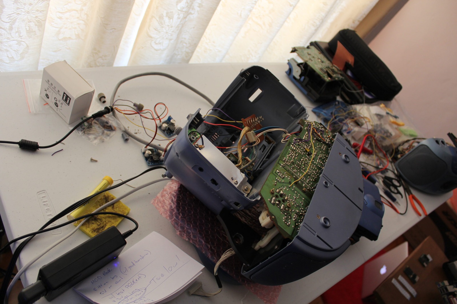
Here’s the Mega CD deck with the grey cable that runs to the Mega Drive / Mega CD section that sits underneath the Aiwa. There are three connectors that join to this board.
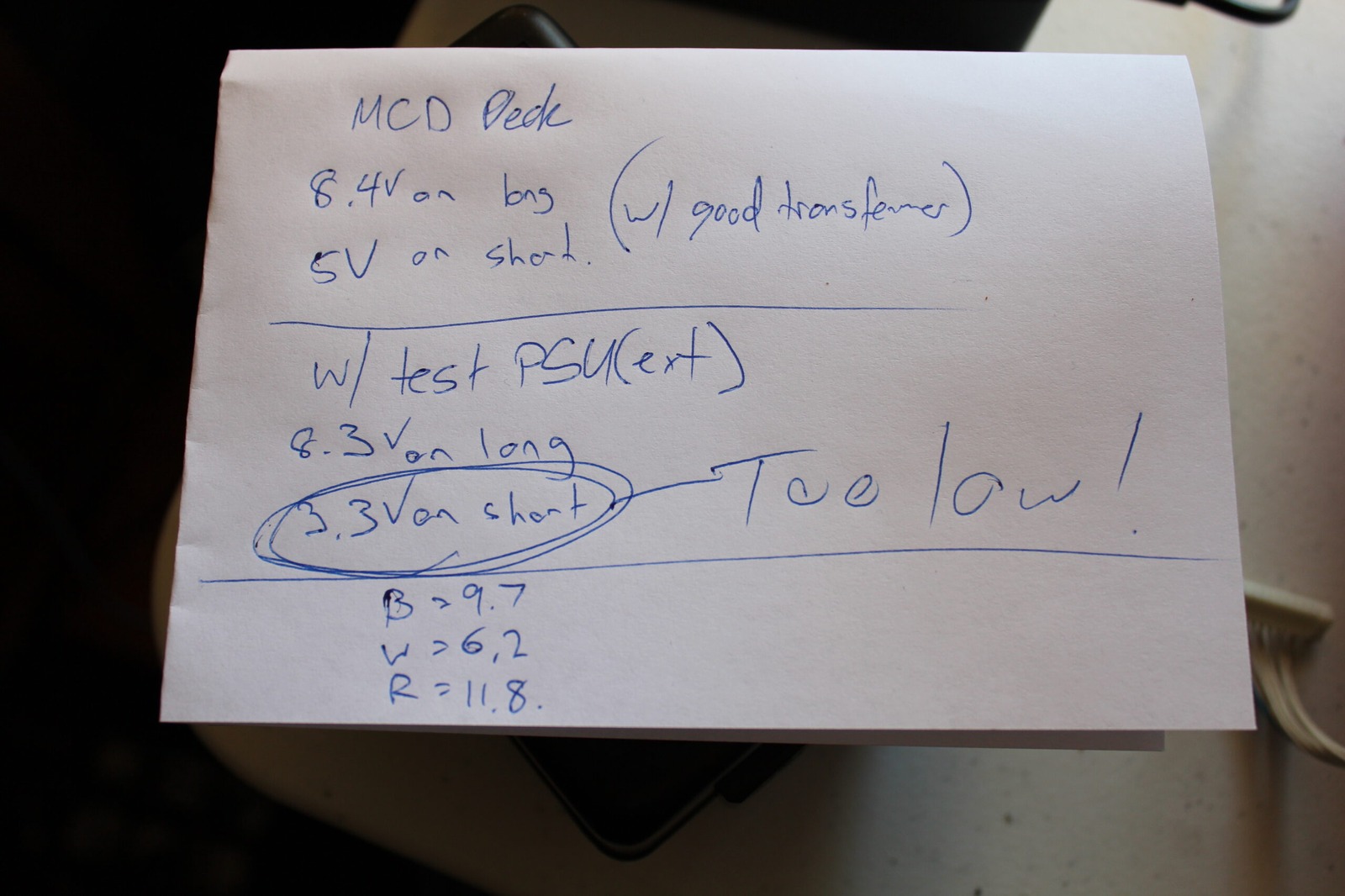
1. A long connector on the right hand side (not in the shot) that powers the CD drive and front control buttons (play, skip, etc). 2. The medium sized left connector which has 8V running through one of the pins. 3. The shortest connector on the right that provides 5V to the Mega Drive section. I found that the 5V was reading only 3.3V and providing very poor image quality. The 8V rail was reading with no issues at all.
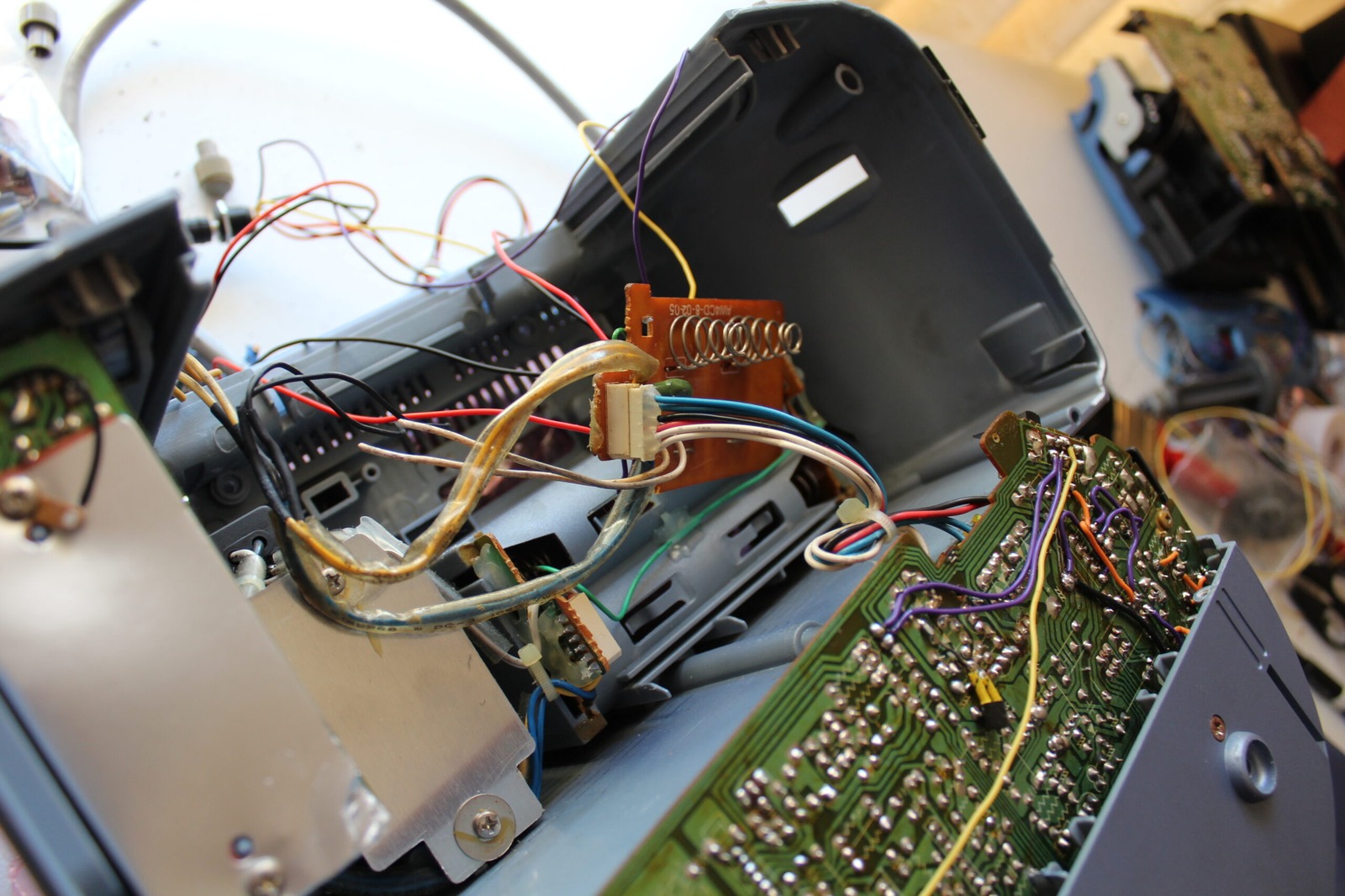
Here’s an overview of the mess with the power connected in. The unit sits upside down and back to front for everything to connect. You can also see we are using the mainboard that was heavily damaged with my great patch up job. The working transformer can be seen in the background still installed.

The back of the unit is our next image and shows the two DC-DC converters connected to power.
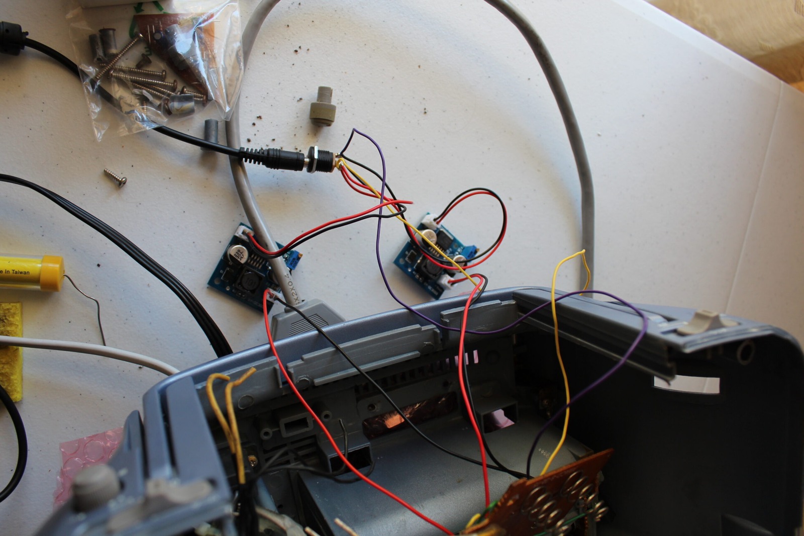
Blue, white, red and black are the colours of the day. I am pretty well acquainted with where they run to on the mainboard now.
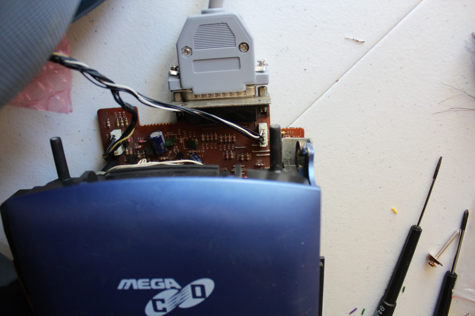
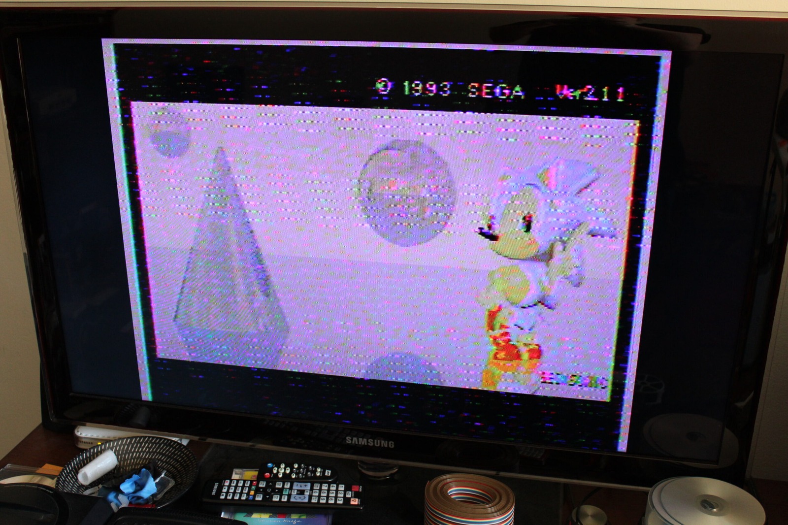
Now to power the unit on and… errr, that’s not looking quite right…
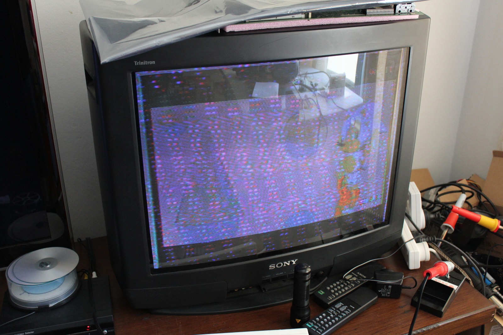
I went ahead and measured the voltages at various points. All the points that ran from the external PSU to the mainboard were the same as the assumed working transformer (uh-oh). I checked the CD deck voltages out of the two pins and found that one was spot on and the other was too low by almost 2V. Checked the 6V voltage regulator and found that it was only outputting 4V. For a 6V regulator I could tell that was not quite right.
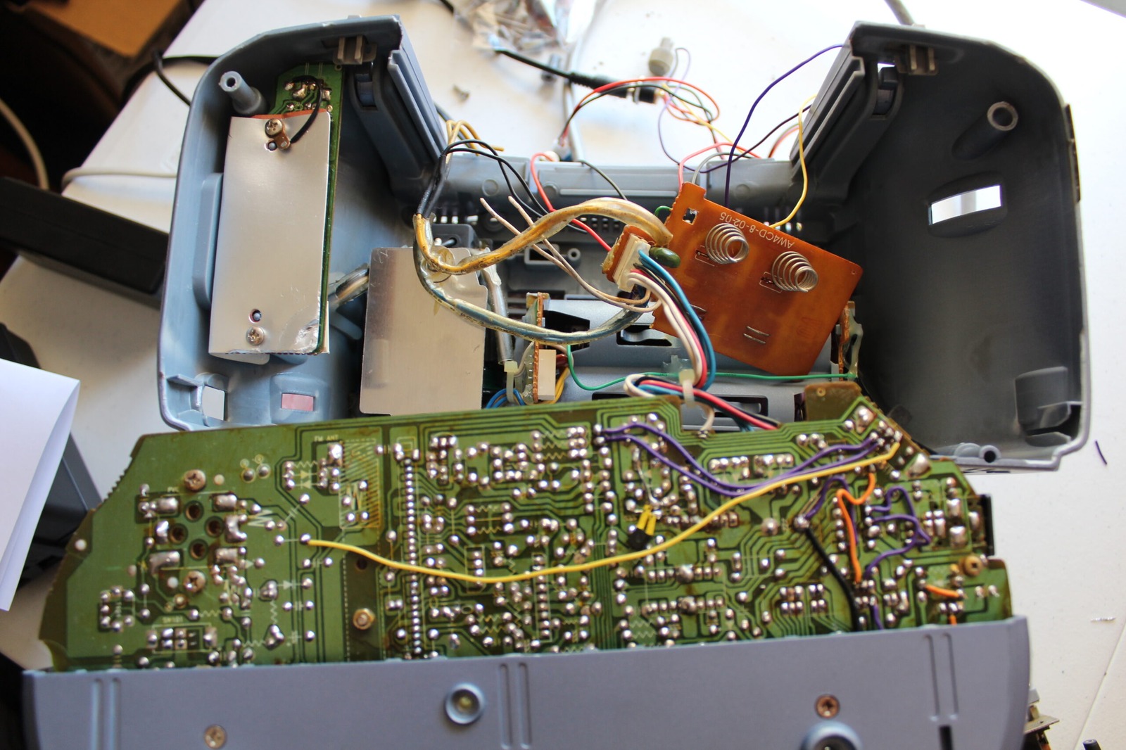
I then tried disconnecting one of the DC-DC stepdown converters to see which one provides the Mega Drive with power. Sure enough it was the white wires running from the mainboard that are fed through to the Mega Drive. No idea what blue does at this point, but I think it is likely CD circuitry for the Mega-CD - more tests to be done on that one yet!
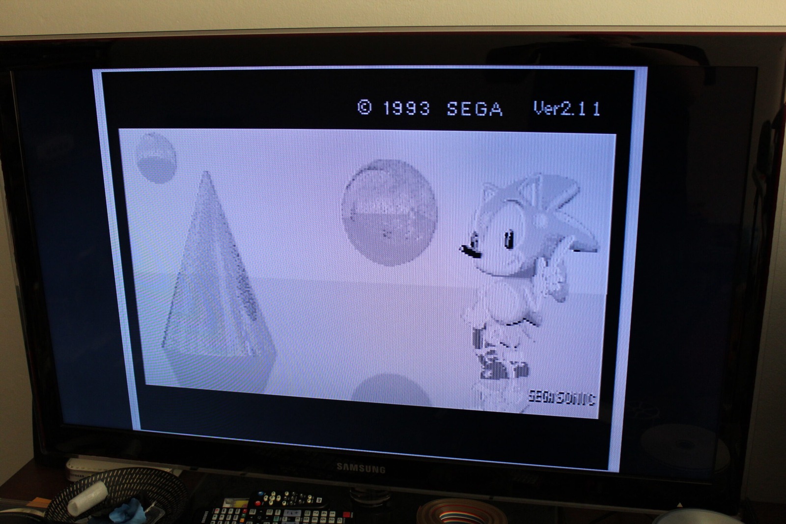
Now if you’ll remember for a moment I was feeding 6.3V to white, 9.75V to blue and 12V to red… you can see we have a problem. I was feeding 6.3V to a voltage regulator that is meant to output at 6V. Impossible mission? Yes! So I tweaked the pot up to 8V to test…
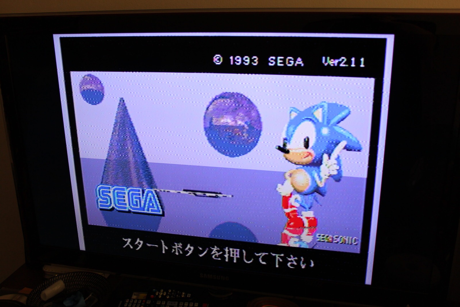
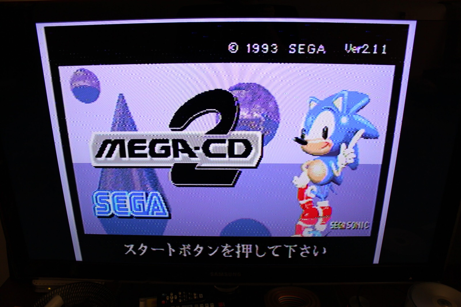
Not only was the picture a million times better, there was also sound off the damaged mainboard. While this is great news, it means that the dodgy looking transformer is rubbish (and now in the bin) and the working one is failing. As it only outputs 6.3V to the white power cables… I think I’m in trouble. However, it does mean that my soldering worked and the mainboard should be fully functional.
That aside though, victory! I’ve got a new laser for the CD deck so I might even get a chance to play a Sega Mega-CD game. And thanks again to Dutchy on ASSEMblergames for reminding me about voltage regulators requiring more than they output. They might have just saved the day!