 Nix McRetro
This modem takes me back to late-2021 when I purchased it. That’s not surprising I guess. This is an AM5690. What does that mean? Probably something along the lines of AutoModem 56kbps V.90. Learn more about this amazing product and why you should buy it on NetComm’s website.
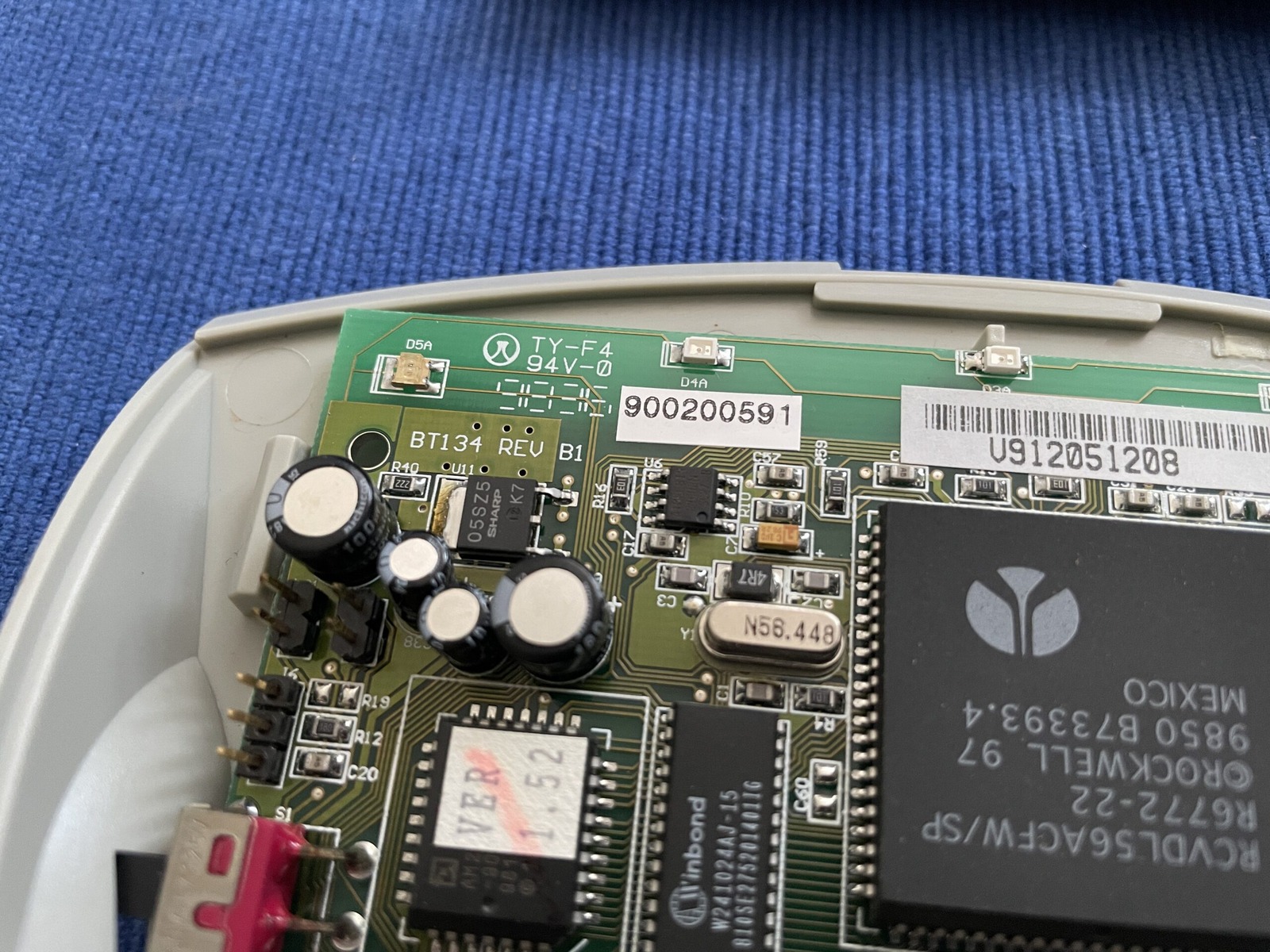
Of note, there’s no power supply specs on the device itself. It was determined to require a 7.5V DC, centre positive power adapter. The power socket on the modem runs into a Sharp PQ05SZ5 voltage regulator for which the datasheet shows roughly 7V DC in will result in 5V DC out. Also should probably mention that the serial number of this modem is 900200591.
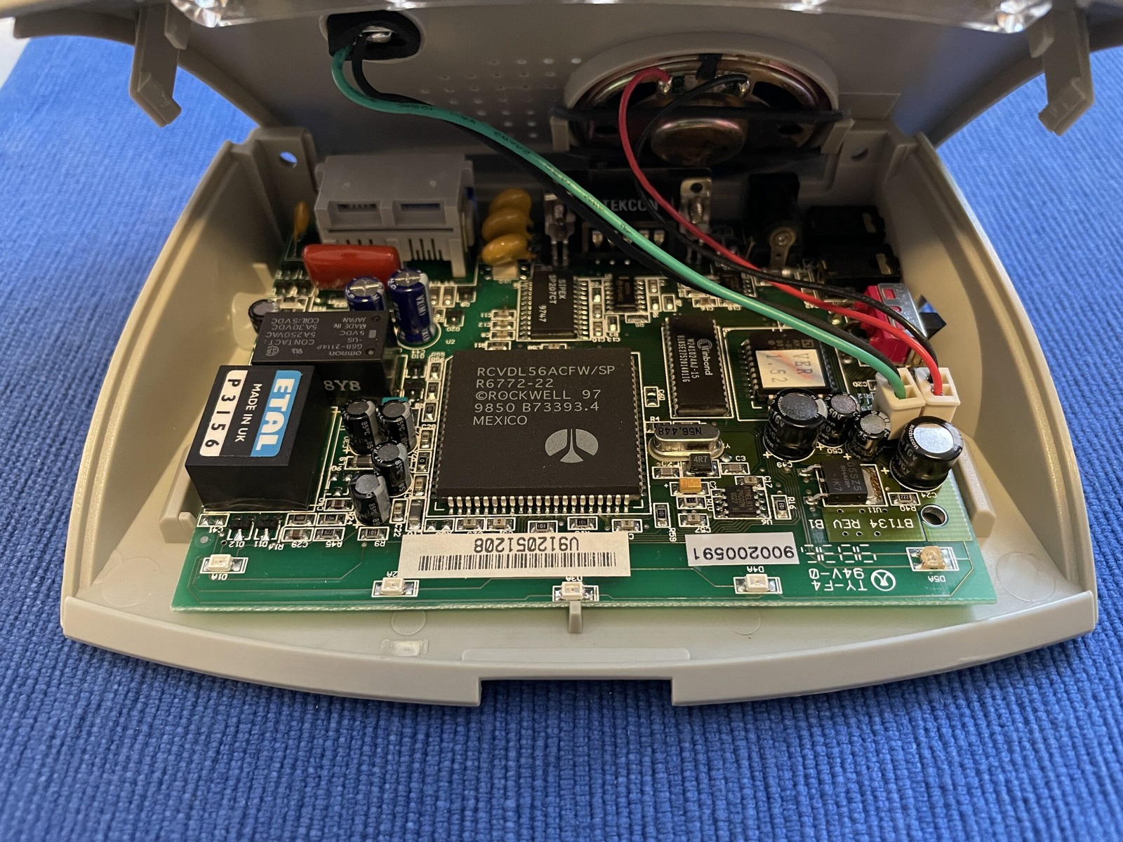
After popping the hood I noticed that the board design looked very familiar. That board number, BT134 REV B1. BT as in Banksia Technology? But the Banksia modems are much more vertical. So I pulled out my Banksia Wave SP 56 Rev.1 (Model Wave56-SP, Serial 13412650) and here’s the two boards in a seizure inducing gif. Edit: I made the gif a little less like a strobe light from a 90s rave.
The BT134 REV B1 is flat as a pancake in the NetComm AM5690, while the BT134 REV B stands tall in the Banksia Wave56-SP Rev 1. Pretty neat! The PCB on the AM5690 got a little longer (wider?) to fit the LEDs and most ports switched angles. Gough Lui’s site has more on Banksia’s history.
So now we know the BT134 REV B1 board is just a variation on the BT134 REV B board. Neat! That also confirms we are using the right power supply for the job thanks to the Banksia being labelled properly externally. It also gives us a minimum milliamp rating of 450mA to modulate and demodulate properly.
Poking around the board a bit more I was delighted to see capacitors. Those who know me, know that I love preventative maintenance. The board design appears to have been designed in week 36, 1998 - 23 years old. So out they came!
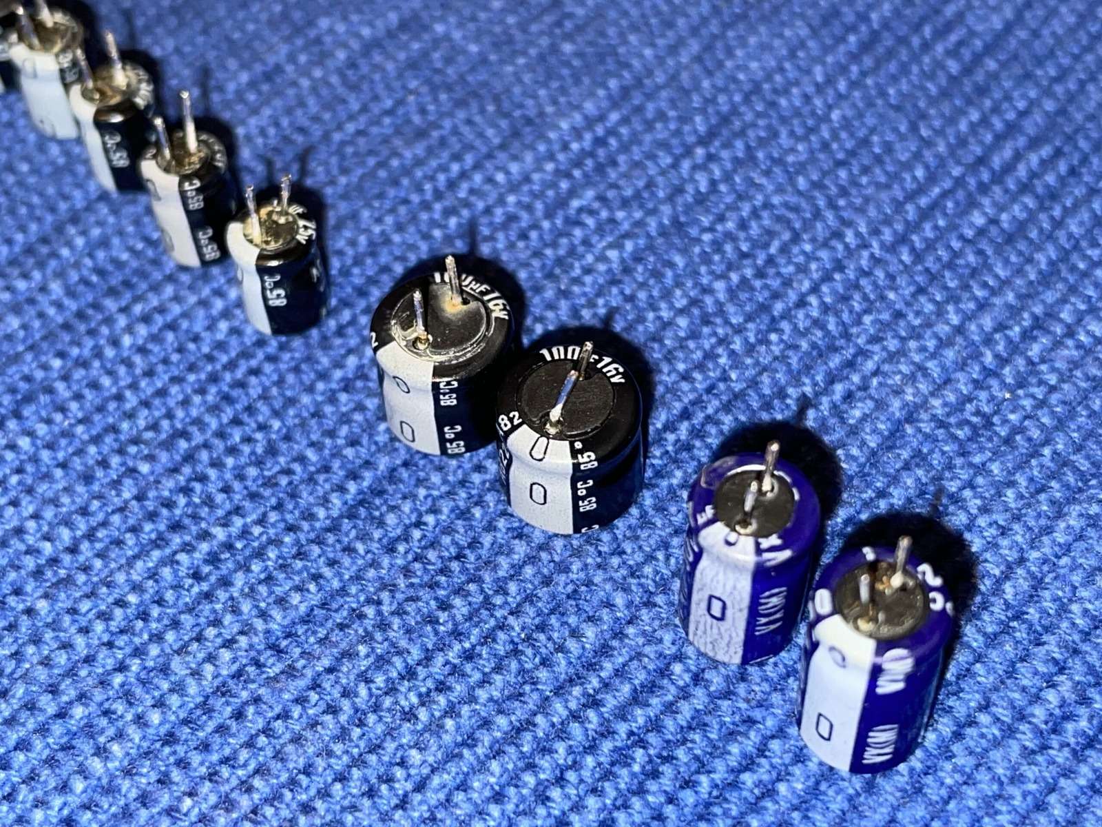
And while I’d love to give Nichicon the benefit of the doubt, but those caps don’t look too happy. Fair, it’s been over two decades, and most of the has probably been in storage. There’s a reason I always recap with Rubycon and Panasonic branded capacitors. They seem to last longer. Even the general purpose Rubys or ELNA ones in Sega’s hardware looks to do very well. Regardless, they were replaced. The photo gallery has been restocked to help quench your thirst for modems too.
The exact initialisation string I used is well… lost. However looking at the Windows drivers for this modem it looks to be the below. Now, whether they are the best ones… I couldn’t say. Trial and error can be fun! As usual, I’ll throw in some ATI (inquiry, information, or interrogation) results. The windows drivers can be found on the file server.
---------- 2021-11-07 16:53:19 +1100: Logging Started ----------
ATZ
OK
AT&FE0&C1&D2W2S95=47-K0S0=0
OK
ATI0
56000
OK
ATI1
070
OK
ATI2
OK
ATI3
V2.210-K56_2M_DLS
OK
ATI4
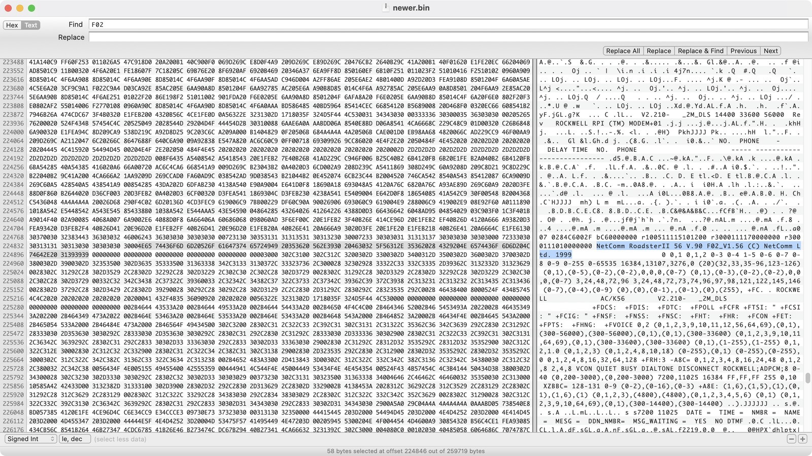
NetComm RoadsterII 56 V.90 F02_V1.56 (C) NetComm Ltd. 1999
OK
ATI5
040
OK
ATI6
RCV56DPF L8570A Rev 47.32/47.32
OK
ATI7
OK
ATDT1234567890
CONNECT 28800
As hinted at above in ATI4, the firmware version is F02_V1.56 and fits neatly inside the 2Mbit flash chip, the AM29F002NB. Thanks to this excellent post by Gough Lui on using Flashcom, we can SRecord to convert these pesky .S37 files to something that has *some* human-readable code using the commands Gough steps through in his guide.
Unfortunately for me the firmware upgrader, am56906.exe, was the same version as what I already had. I reflashed it anyway as the retention for this chip, the AM29F002NB, is only 20 years… at 125 degrees… Celsius! I’m not sure how it was stored in the past. So if it was kept in a fire pit for the last 20 years, I’d rather be safe than sorry I guess! 🤣
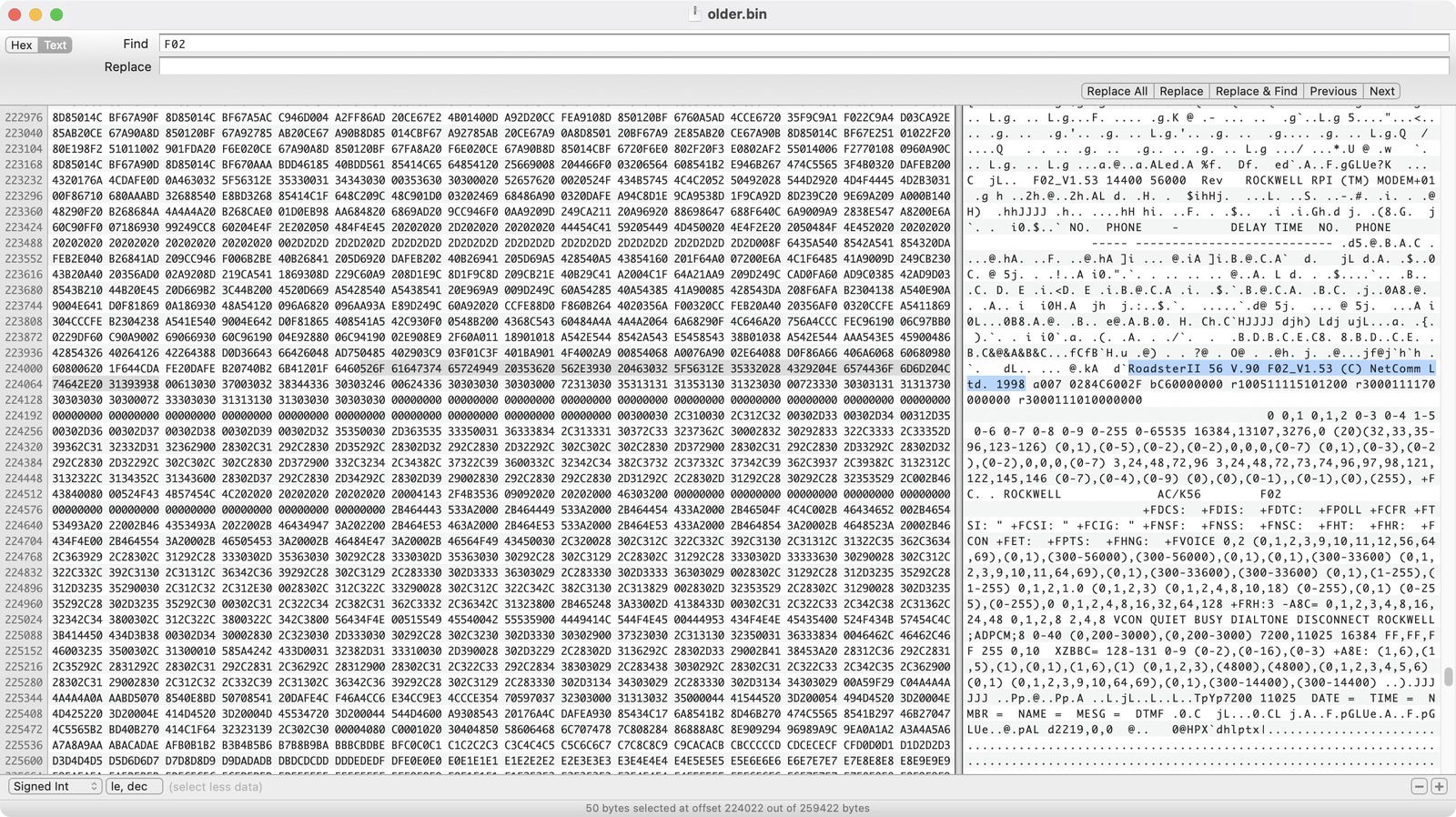
The am56906.exe installer also included an older version of the flash ROM - V1.53. Good on NetComm for being cautiously optimistic with their firmware. It looks like this modem originally shipped with V1.52 installed, so someone else upgraded it along the way, way back in the day!
Next up is a listing of the electrolytic capacitors replaced and what they were replaced with i.e. their manufacturer part numbers. All 11 capacitors were replaced in November 2021. While the formatting isn’t too web friendly, copy the raw text out and paste it into a non-rich text editor (Such as Notepad or TextEdit - in plain text mode) and you’ll probably be fine. 😄
Location	Value	Voltage		Height	Width	Notes
C24			100uF	16V			7mm		6mm		16ML100MEFC6.3X7
C49			100uF	16V			7mm		6mm		As above
C44			47uF	50V			11mm	6mm		50YXJ47M6.3X11
C45			47uF	50V			11mm	6mm		As above
C50			10uF	50V			7mm		5mm		50YXF10MEFC5X11 - Taller at 11mm(h)
C38			10uF	25V			7mm		4mm		25ZLG10MEFC4X7
C30			10uF	25V			7mm		4mm		As above
C27			10uF	25V			7mm		4mm		As above
C14			10uF	25V			7mm		4mm		As above
C21			10uF	25V			7mm		4mm		As above
C46			10uF	25V			7mm		4mm		As above

All electrolytic capacitors are radial.
Lead spacing is 2-2.5mm on most.
Use caution under the speaker as 11mm(h) capacitors will not have clearance.
Special thanks to:
- Doge Microsystems as always for their VoIP configuration guides
- Gough’s Blog.
This modem has been donated to the Australian Computer Museum Society (ACMS).