Back in mid-2022 I was given this modem as a gift, and while I wasn’t looking for any V.92 modems I figured I’d document it. While I tend to be a little more V.32 or V.34 inclined, I am open to the idea of V.92 modems doing the work of a V.34 modem. Maybe I just really like the old Rockwell chipsets before they were floated on the stock exchange becoming Conexant Systems.
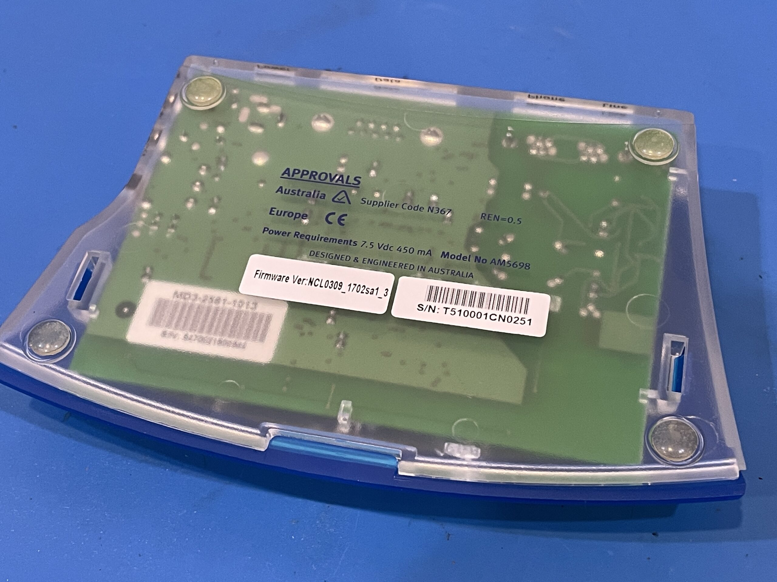
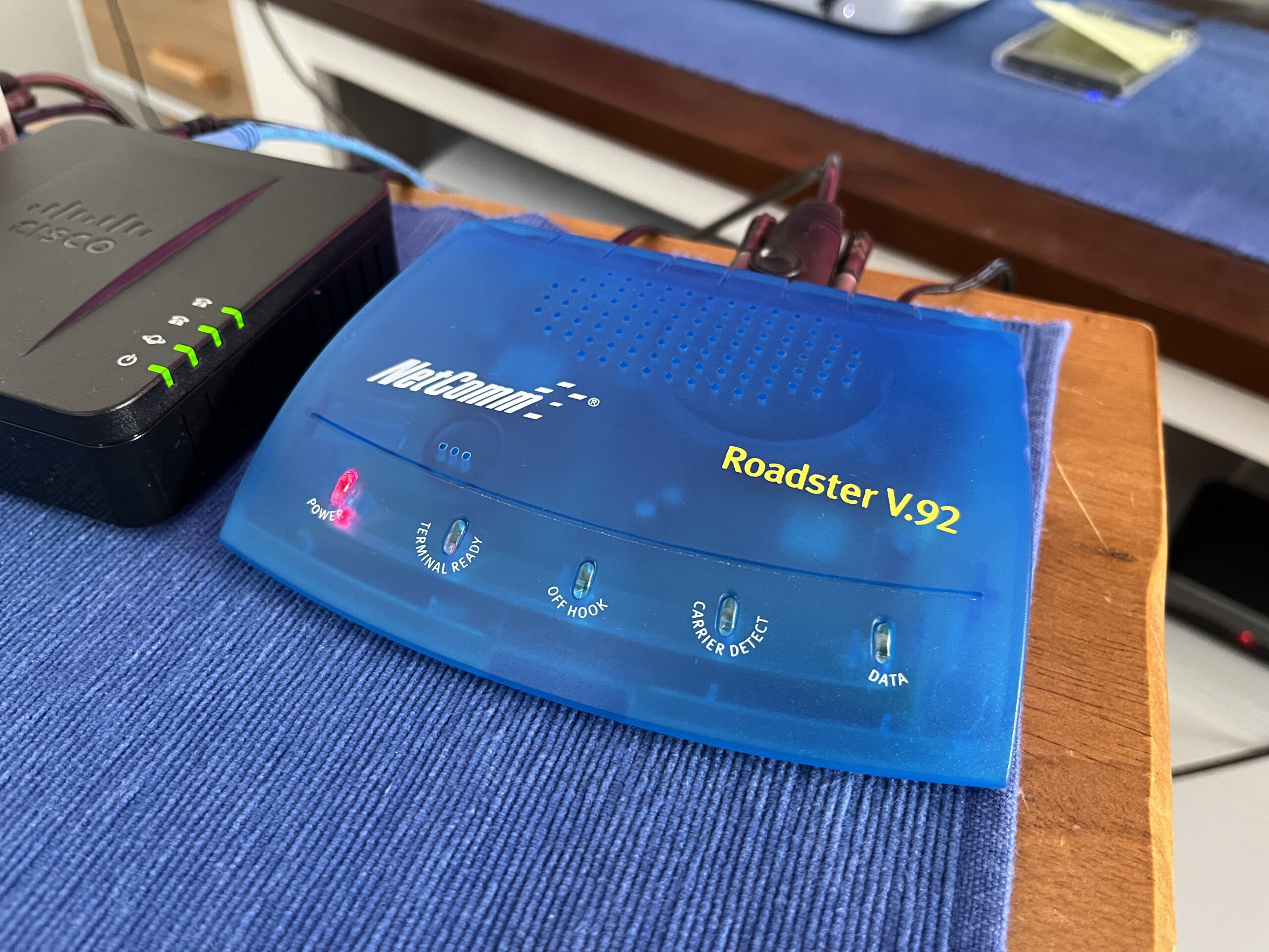
Externally it is marked as a NetComm Roadster V.92 model AM5698. The power supply required is 7.5V DC centre-positive at a minimum of 450mA which seems to be the standard for the NetComm AM56XX series and the related Banksia Wave SP family of modems.
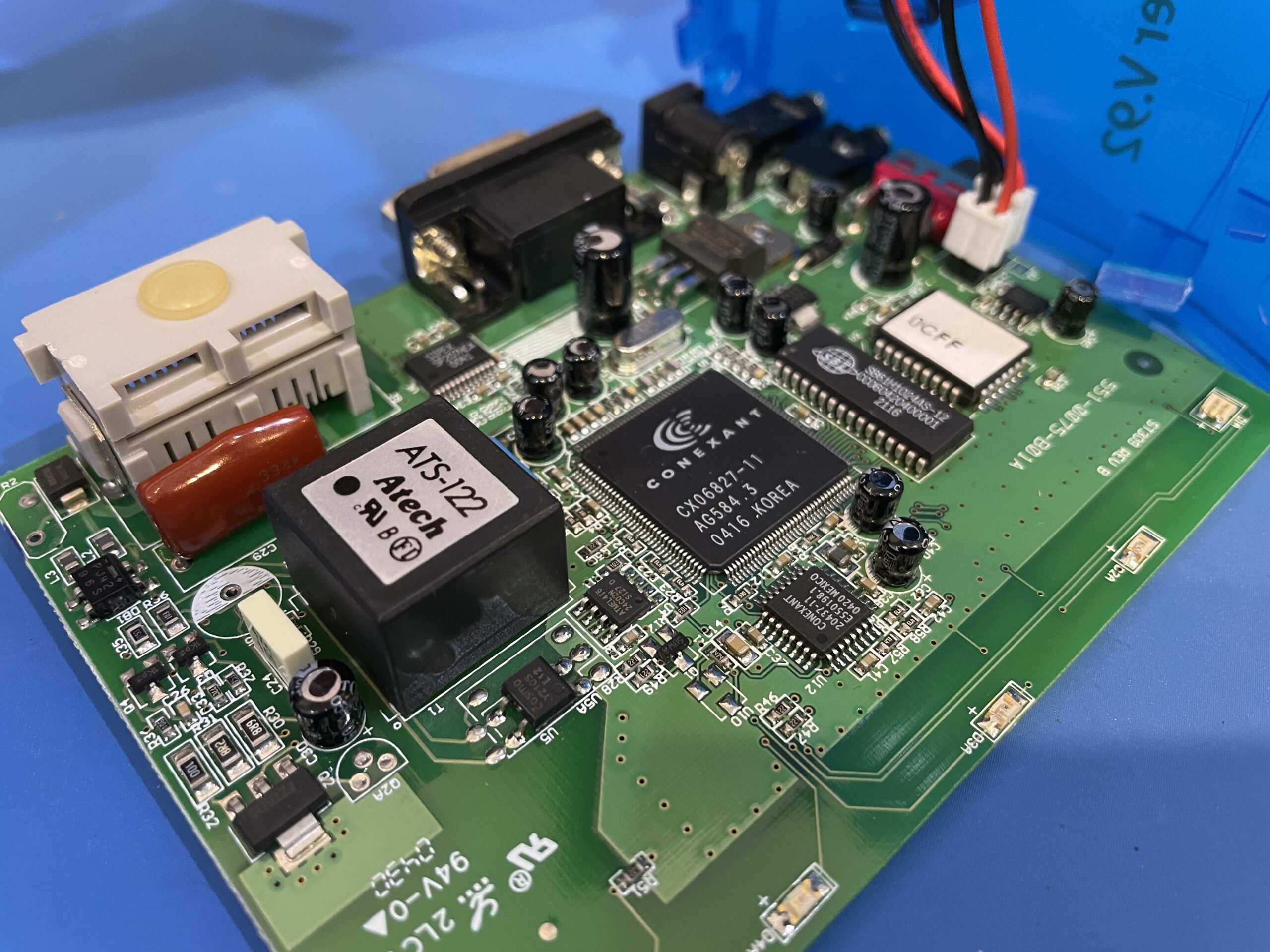
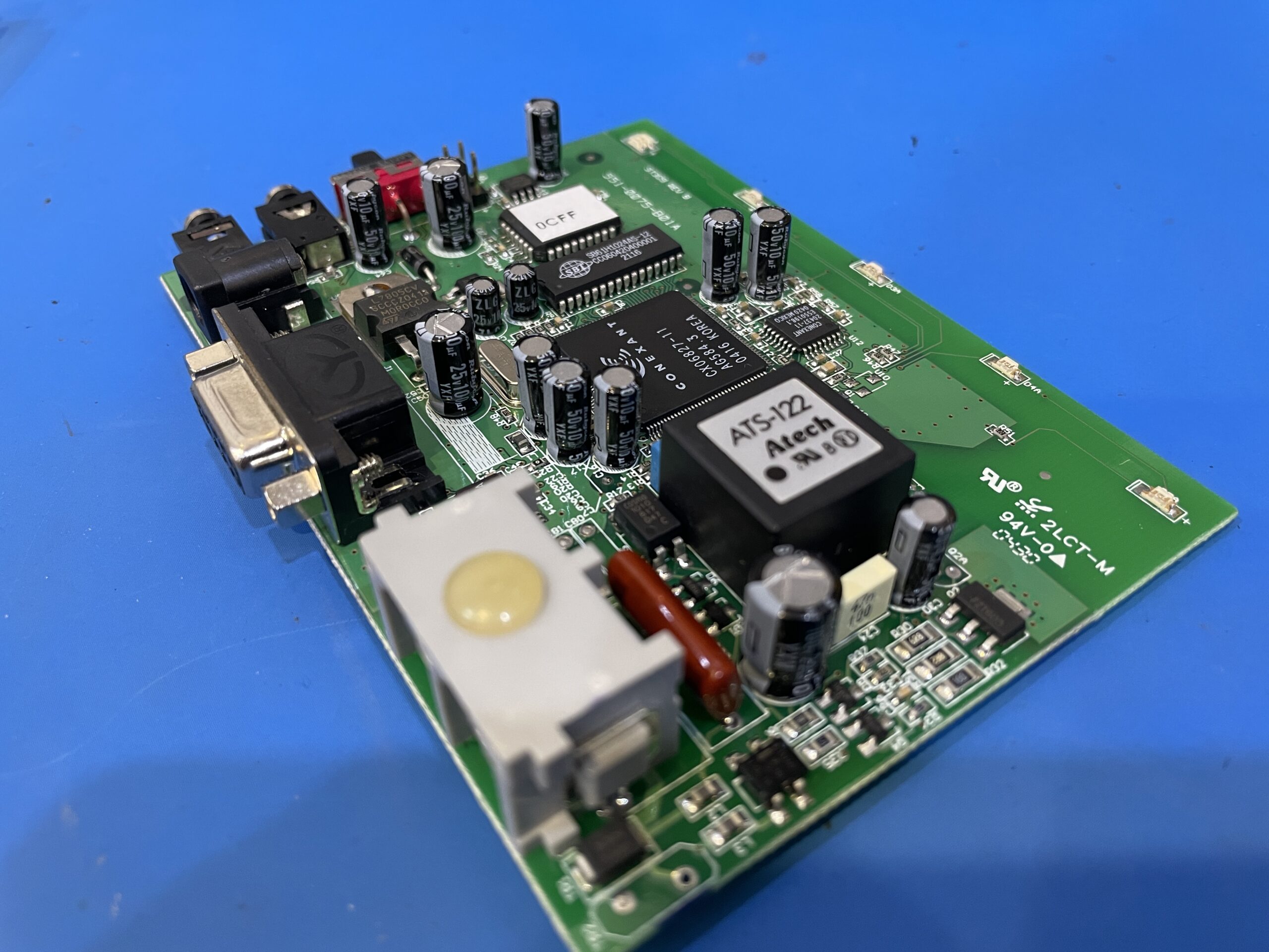
Internally we can see the PCB is marked with ST309 REV B. Most of the date codes on the board indicate a manufacturing date of mid-late 2004 – which makes this quite a late revision and under 20 years old it came across my desk. 13 capacitors, most if not all were STONE branded. Make note of those capacitor heights. I might have made a slight misstep when replacing them. More on that later.
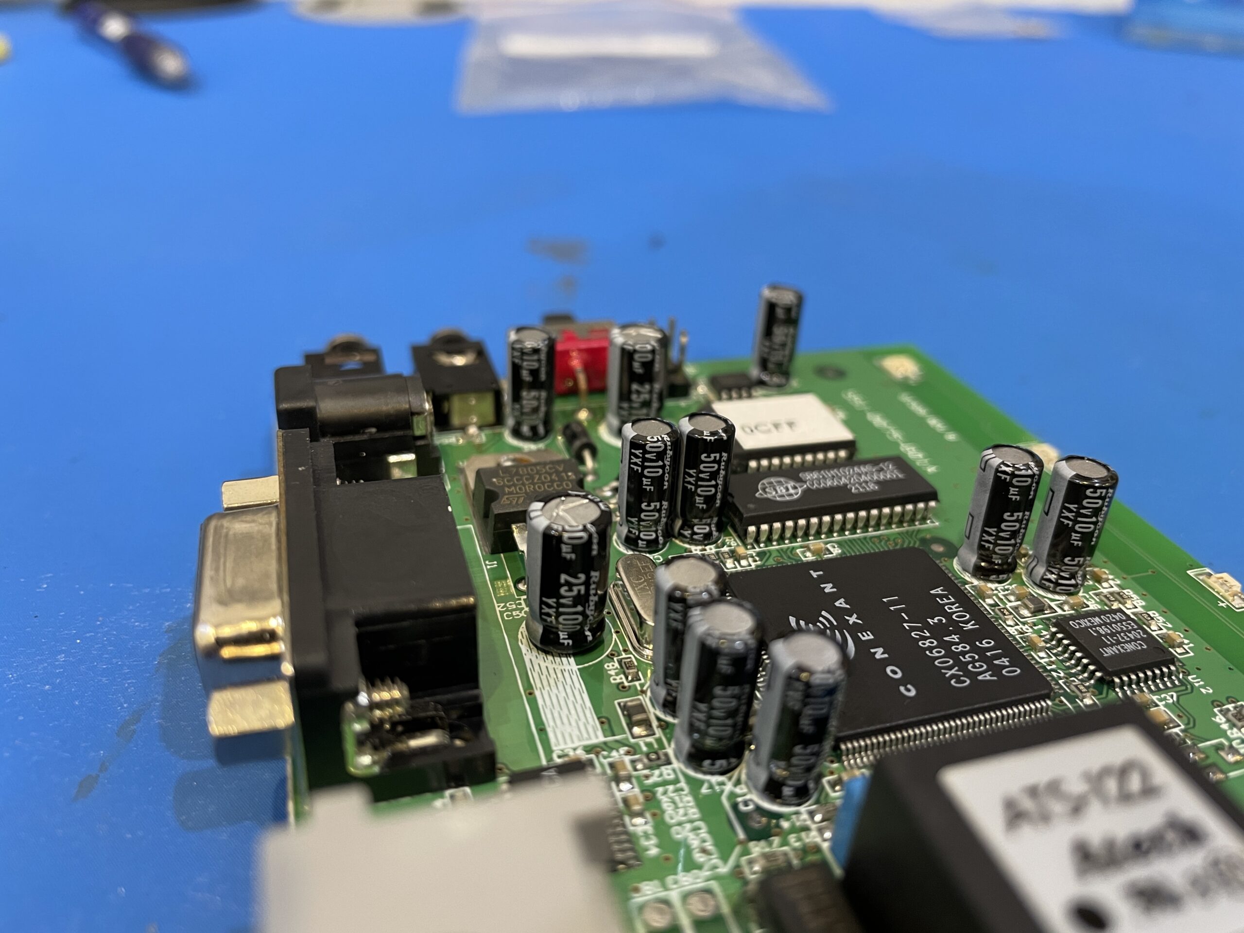
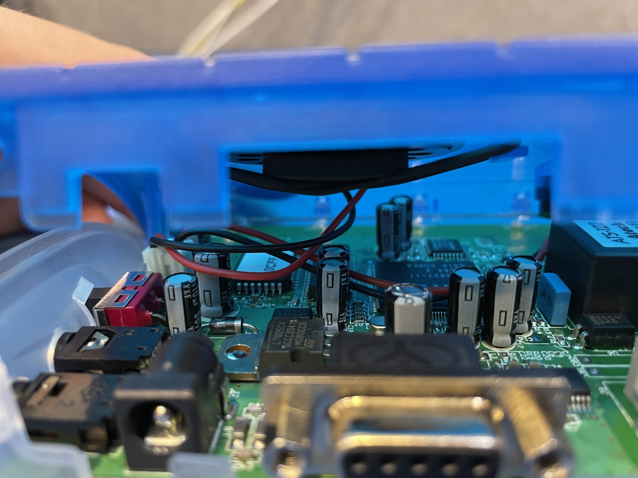
Oh, what’s that? We’re just jumping straight into the capacitors on this one? Well there you go! Mostly Rubycon YXF series were used, but look what happens when I try to put the case back together…
Dammit! That speaker does not have the clearance it needs. I need the ultra short capacitors. Slap in some shorter ZLG series caps and like magic…
Perfect! Interestingly most of the affected caps were 10uf at 25V but I might have derated them a little to 50V, which in this case made them not quite fit right… 😅 The capacitor at C25 is a 22uF with a 63V rating. Now given it is nearest to the power input it’s probably running at ~7.5V which gives plenty of leeway.
It was of interest it was a bipolar, or non-polar, capacitor. Jon informed me that it was likely because the factory would have just used whatever they had on hand to save on costs or to meet production. When the capacitor was removed, the silkscreen revealed a polarised cap confirming his theory.
Next up we have the ATI (inquiry, information, or interrogation) results. This give us the active firmware version – this wasn’t dumped because I didn’t have much interest in doing it at the time. That said, it might be available through archive.org as an available firmware update. You’ll need to scour the archives to track that down though.
---------- 2022-10-02 20:47:01 +1100: Logging Started ----------

AT&F
OK

AT&FE0V1S0=0&C1&D2+MR=2;+DR=1;+ER=1;W2
OK

ATI0
57600
OK

ATI1
255
OK

ATI2
OK

ATI3
ACF3_V1.702-V90_P21_FSH_LL
OK

ATI4
NetComm V.92 Modem V1.702SA1
OK

ATI5
09
OK

ATI6
RCV56DPF-PLL L8571A Rev 47.00/34.00
OK

ATI7
OK

ATI8
ERROR

ATDT1234567890
CONNECT 28800
The capacitors were replaced in this modem in September 2022. The parts listed below are manufacturer part numbers. The formatting isn’t too web friendly, copy the raw text out and paste it into a non-rich text editor (Such as Notepad or TextEdit – in plain text mode) and you’ll probably be fine. 😄
Location	Value	Voltage		Height	Width	Notes
C50		100uF	25V		12mm	6mm	25YXF100MEFC6.3X11
C67		100uF	25V		12mm	6mm	As above
C25		22uF	63V		12mm	8mm	100YXM22MEFC8X11.5 - Non-polar but had silkscreen for polar, YXM Series, 100V upgrade.
C30		4.7uF	50V		6mm	5mm	50YXF4R7MEFC5X11

C65		10uF	25V		6mm	4mm	50YXF10MEFC5X11 - YXF Series, 50V upgrade.
C64		10uF	25V		6mm	4mm	As above
C63		10uF	25V		6mm	4mm	As above
C62		10uF	25V		6mm	4mm	As above
C15		10uF	25V		6mm	4mm	As above
C16		10uF	25V		6mm	4mm	As above
C17		10uF	25V		6mm	4mm	As above

C18		10uF	25V		6mm	4mm	25ZLG10MEFC4X7 - Height restricted.
C19		10uF	25V		6mm	4mm	As above


All electrolytic capacitors are radial.
Lead spacing is 2-2.5mm on most.
Use caution under the speaker as 11/12mm (h) capacitors will not have enough clearance.
As always you can see more pictures in the photo gallery and grab any drivers from the file server. I’ve put an iso image up of the entire driver disc as well but you shouldn’t need much more than the above init string to get dialling.
This modem has been donated to the Australian Computer Museum Society (ACMS).
