 Nix McRetro
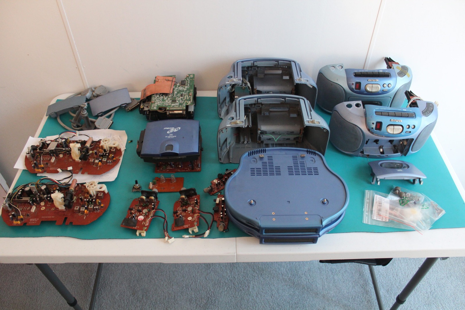
I’ve been replacing capacitors in my Aiwa Mega-CD CSD-GM1, and naturally there are quite a few of the little guys scattered throughout the machine. Rather than keep going back to the circuit boards every time I need to work out which capacitor goes where, I’ve been keeping a record of the values as I remove and replace them. Hopefully this will save a bit of work the next time I decide to pull one of these things apart!
I’ve got two CSD-GM1 units here, with revision 1 and revision 2 mainboards. Interestingly, the boards appear to be extremely similar as far as their electrolytic capacitors are concerned. They might even be identical in this area, although there’s one little catch. These machines have both had interesting lives before arriving on my workbench, and I can’t guarantee that every capacitor I found was still the original factory part.
Somebody might have been in there before me, so these are the values recorded from the actual boards I’ve been working on rather than a definitive parts list for every Aiwa CSD-GM1 ever manufactured. Even so, it’s useful having a record of what I’ve found, especially when I’m trying to compare the two revisions.
Anyone who has followed my earlier Aiwa repair adventures will know that getting these machines working again has involved considerably more than swapping a few capacitors. We’ve had damaged tracks, power problems, recapping and all sorts of other interesting surprises. At least having two units gives me something to compare things against. Sometimes one broken machine is the best source of information for another broken machine!
Capacitor Spreadsheet
I also made the capacitor record available as a spreadsheet. It should come in handy for anyone else working on one of these rather unusual Sega machines, particularly if they’ve got a board that’s been attacked by leaking capacitors. The individual repair articles and photographs also record the boards I worked on.