 Nix McRetro
These are my SuperCIC installation notes and photographs for an SNSP-CPU-02 board with the PAL F413A CIC. The original article left the PIC programming instructions and circuit diagram as placeholders, so it is not a complete standalone guide. Use Wolfsoft’s installation guide and the SuperCIC project documentation linked below alongside these photographs.
Console serial: UP15971140
You can find the full photo gallery. Look for Super Nintendo UP15971140.
The console-side SuperCIC lock uses a programmed PIC16F630 and provides switchless region control, with 50 Hz, 60 Hz and automatic modes.
Parts I used
- PIC16F630 programmed with the SuperCIC lock firmware
- 30 AWG Kynar wire
- X-Acto knife or fine jeweller’s flat-blade screwdriver for lifting pins
- PIC programmer (I used a GQ-4X)
- 5mm dual-colour LED
- suitable current-limiting resistors for the LED
Board connections
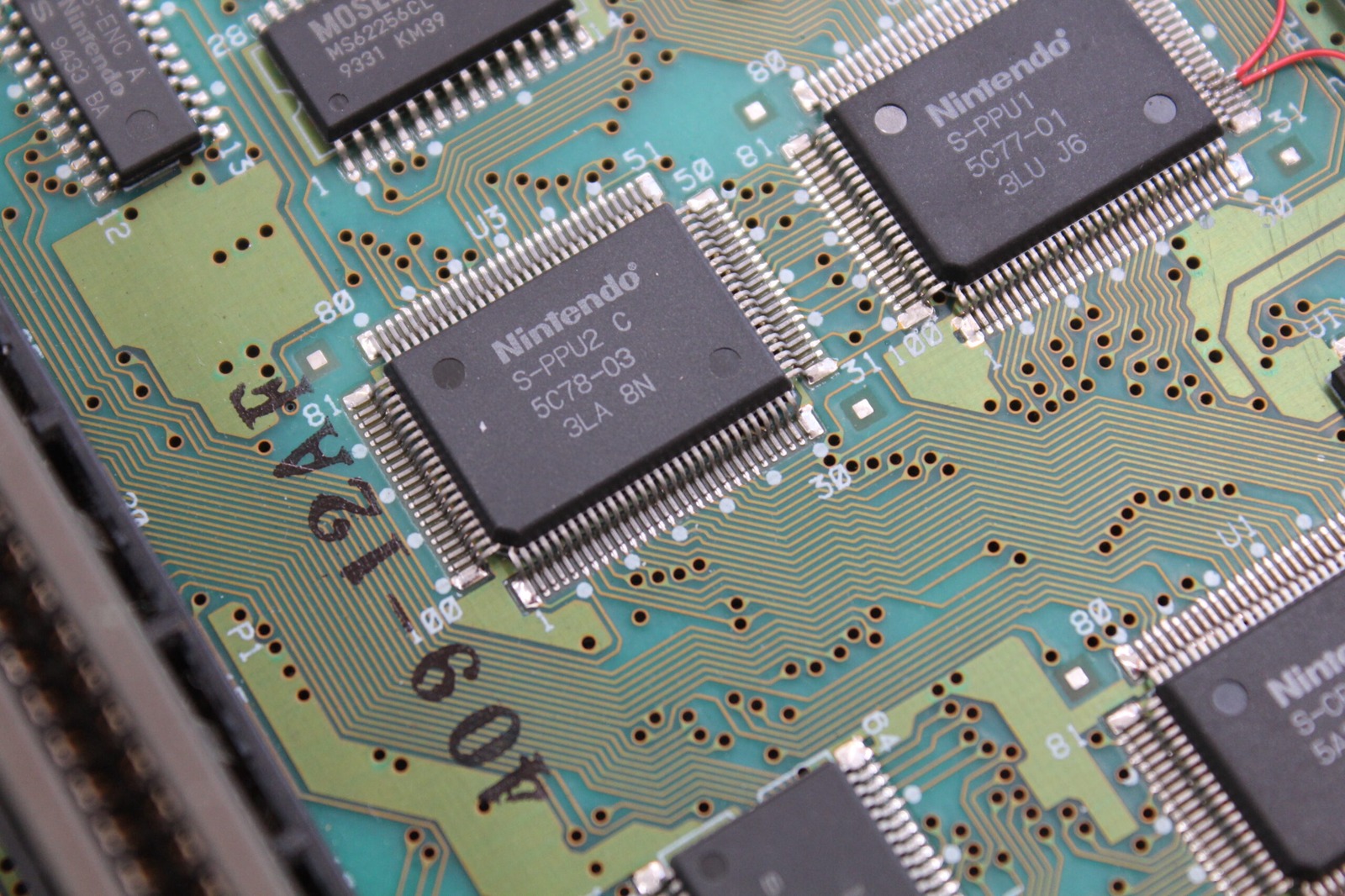
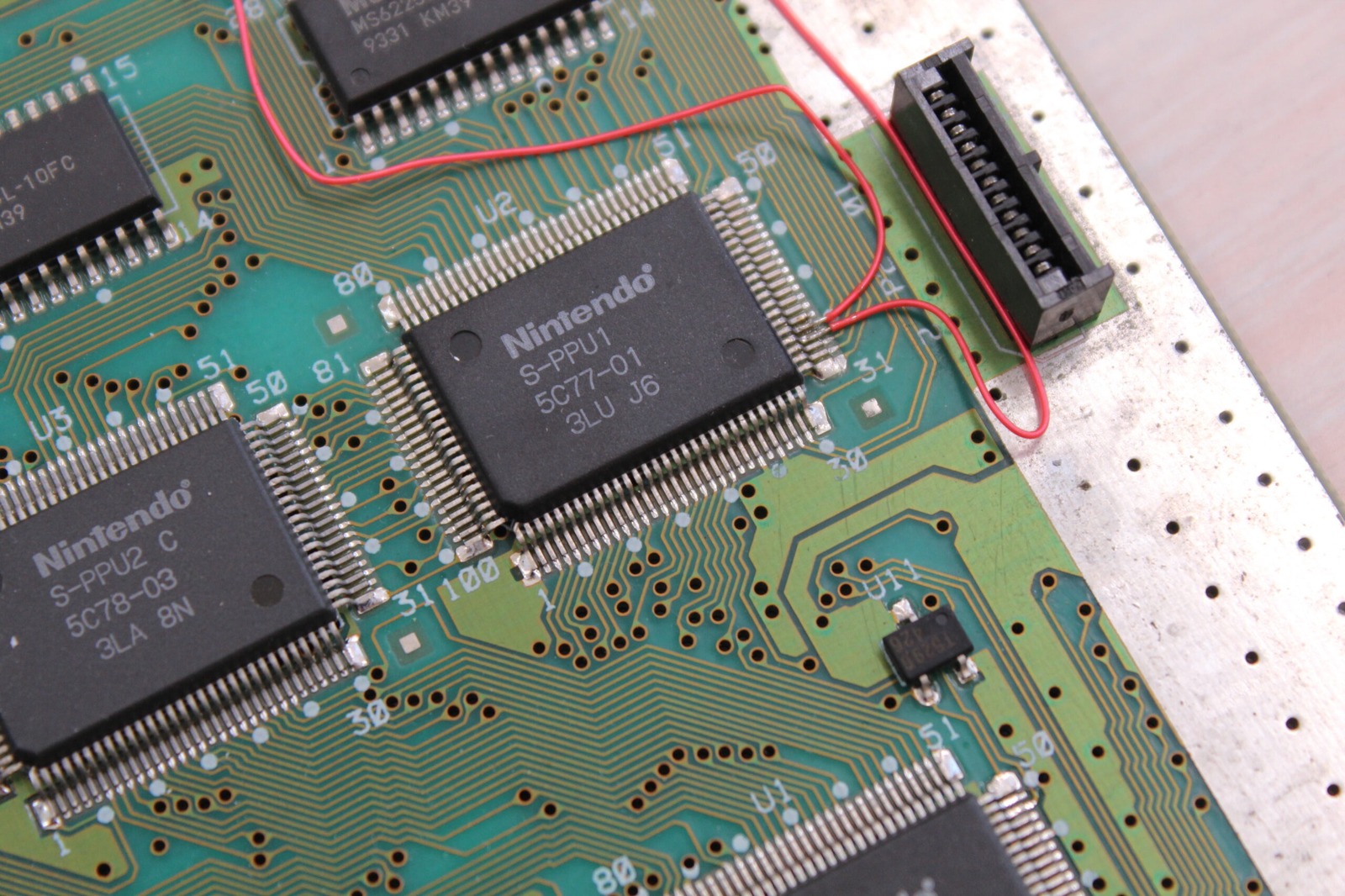
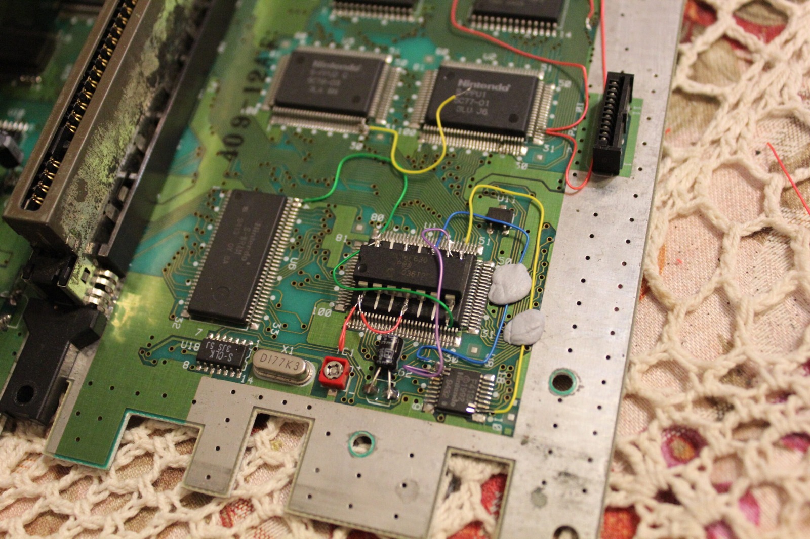
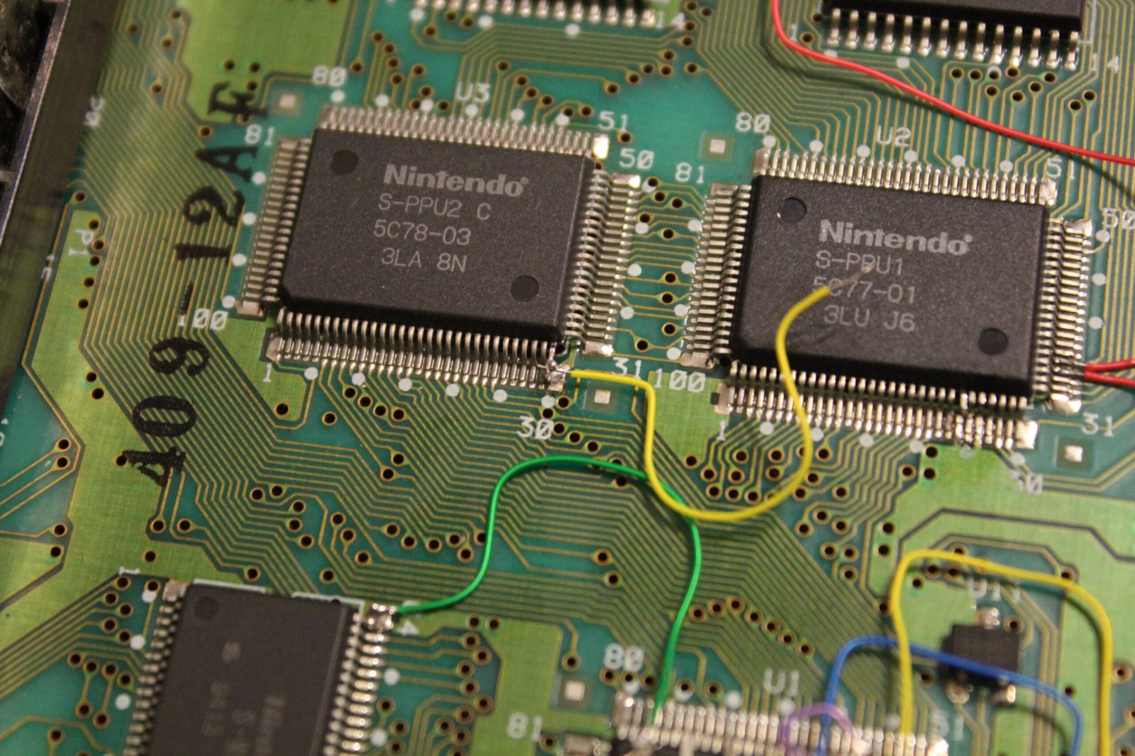
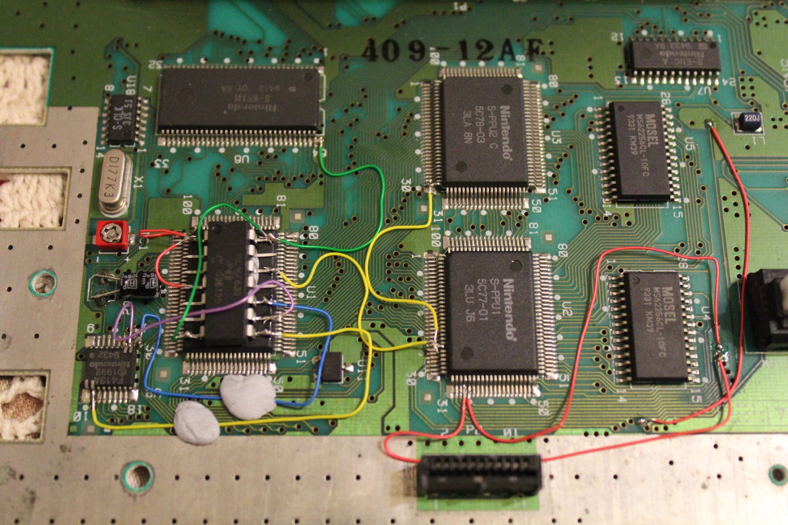
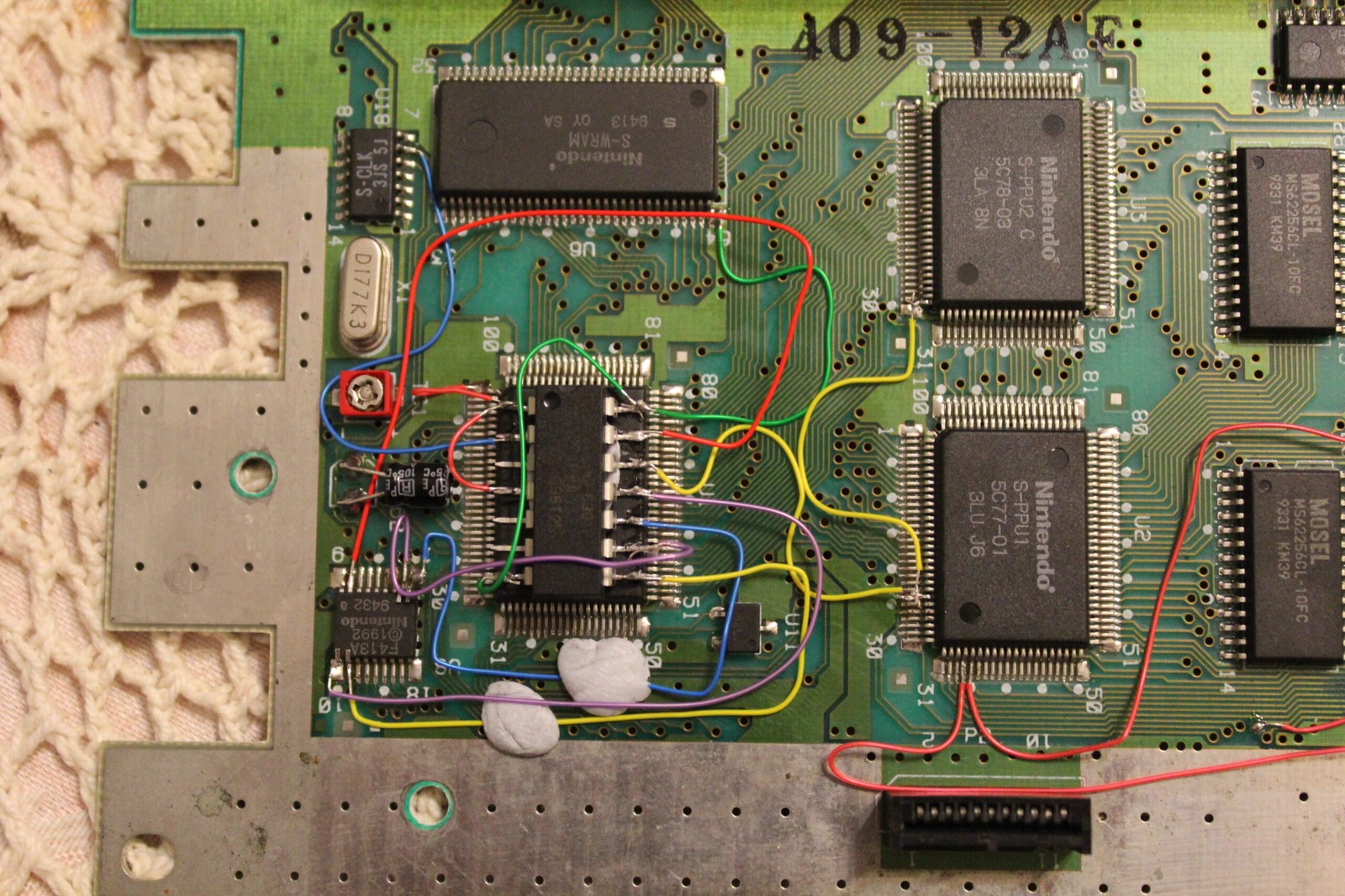
Locate PPU1, PPU2 and the F413A CIC. Don’t mind the red wires leaving my PPU1. They were already there to repair corroded traces near the reset switch.
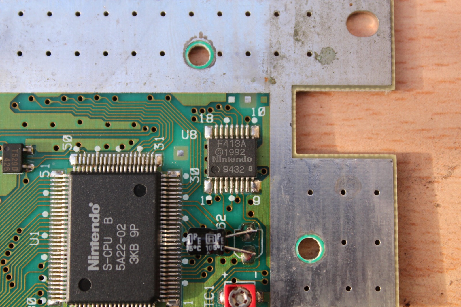
F413A CIC
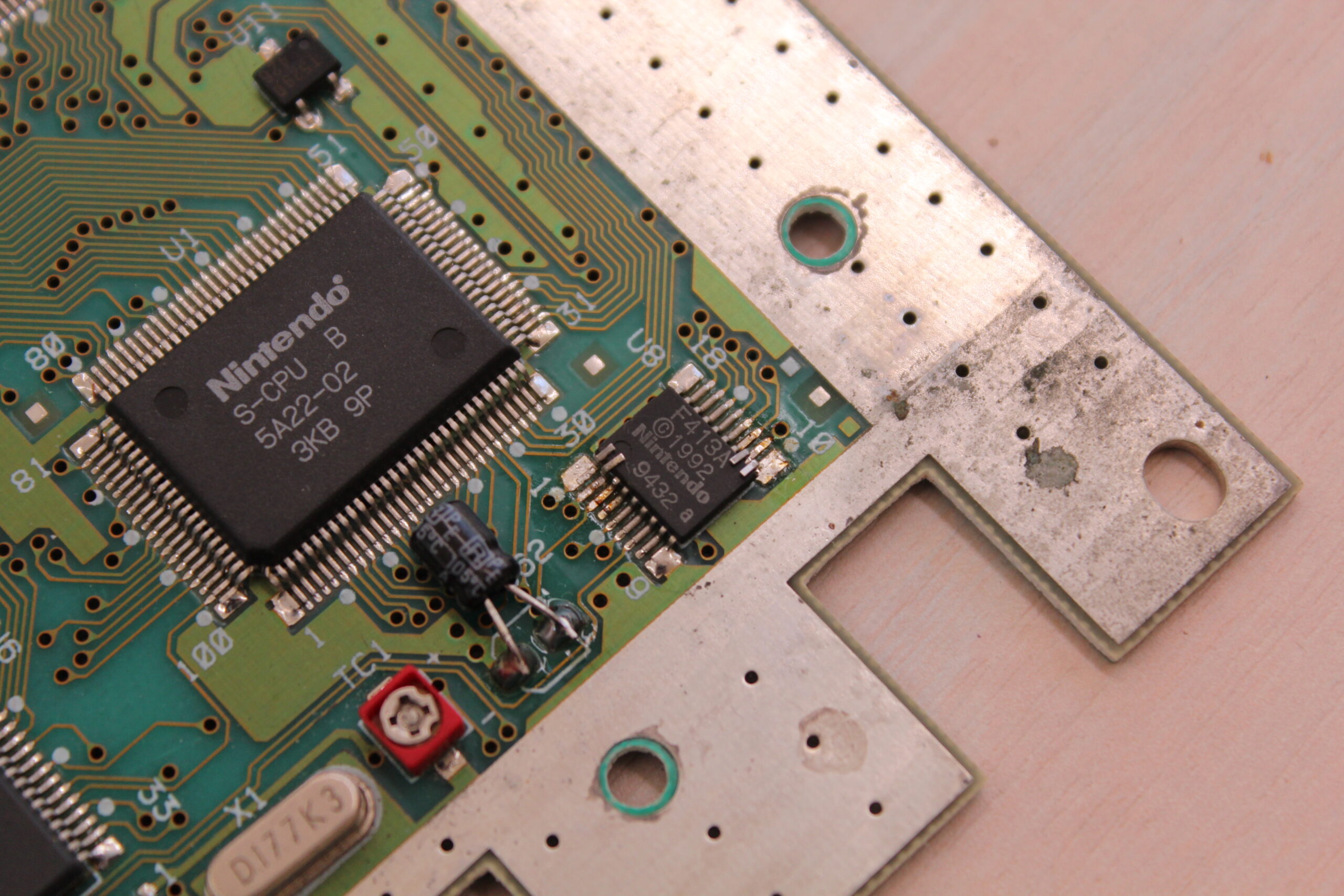
On this installation I left the original F413A on the board and lifted pins 1, 2, 10 and 11 so that they no longer contacted their pads. Wolfsoft’s guide describes this as one of two approaches; the other removes the original CIC completely.
Video mode connections
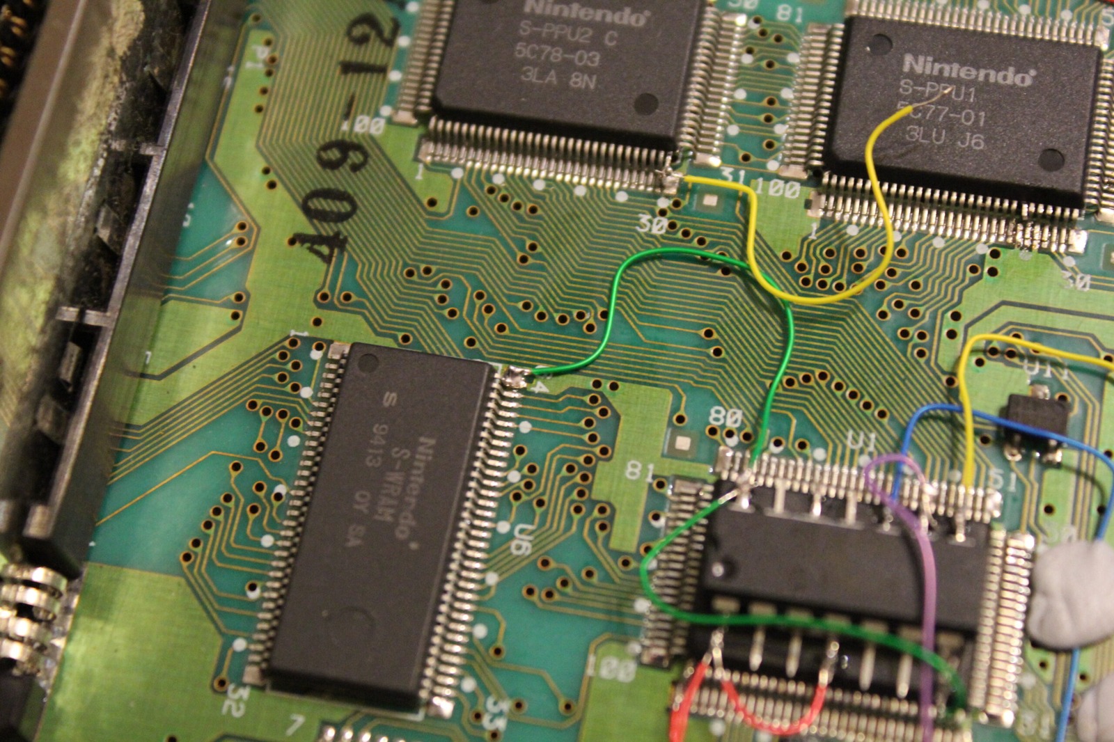
On this multi-chip board, lift PPU1 pin 24 and PPU2 pin 30 so that both are isolated from their original board connections before wiring them to the SuperCIC.
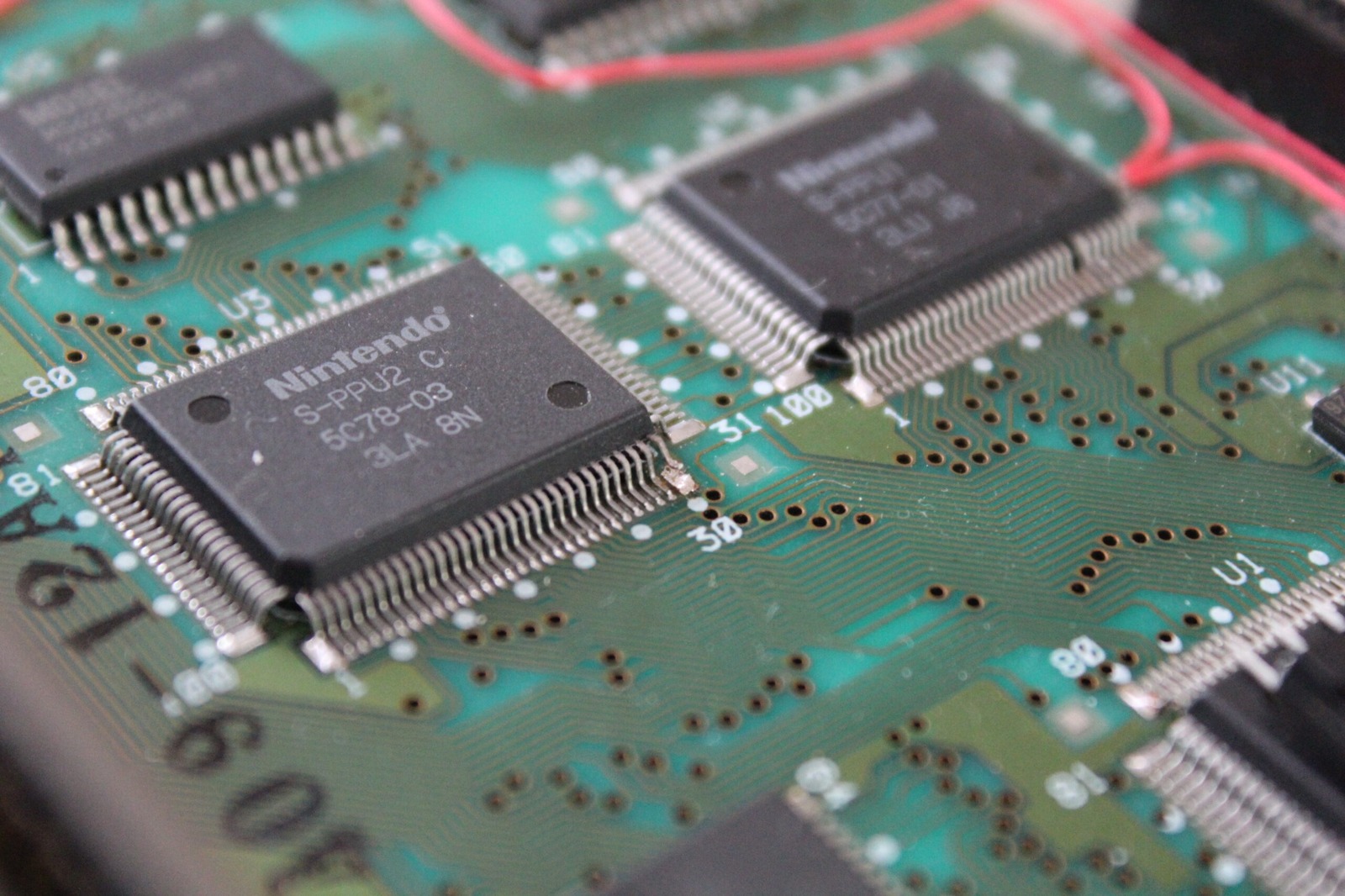
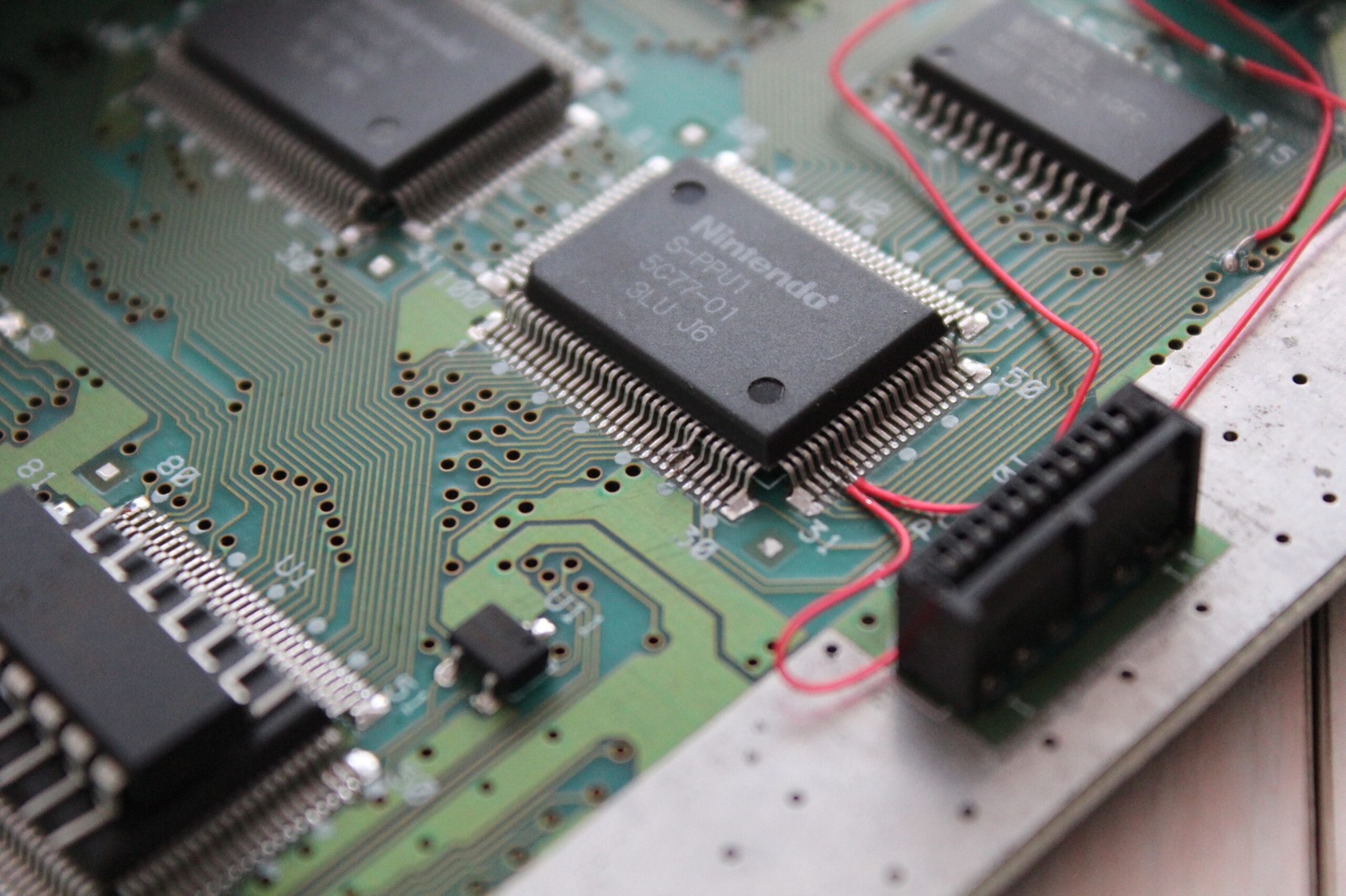
PIC placement
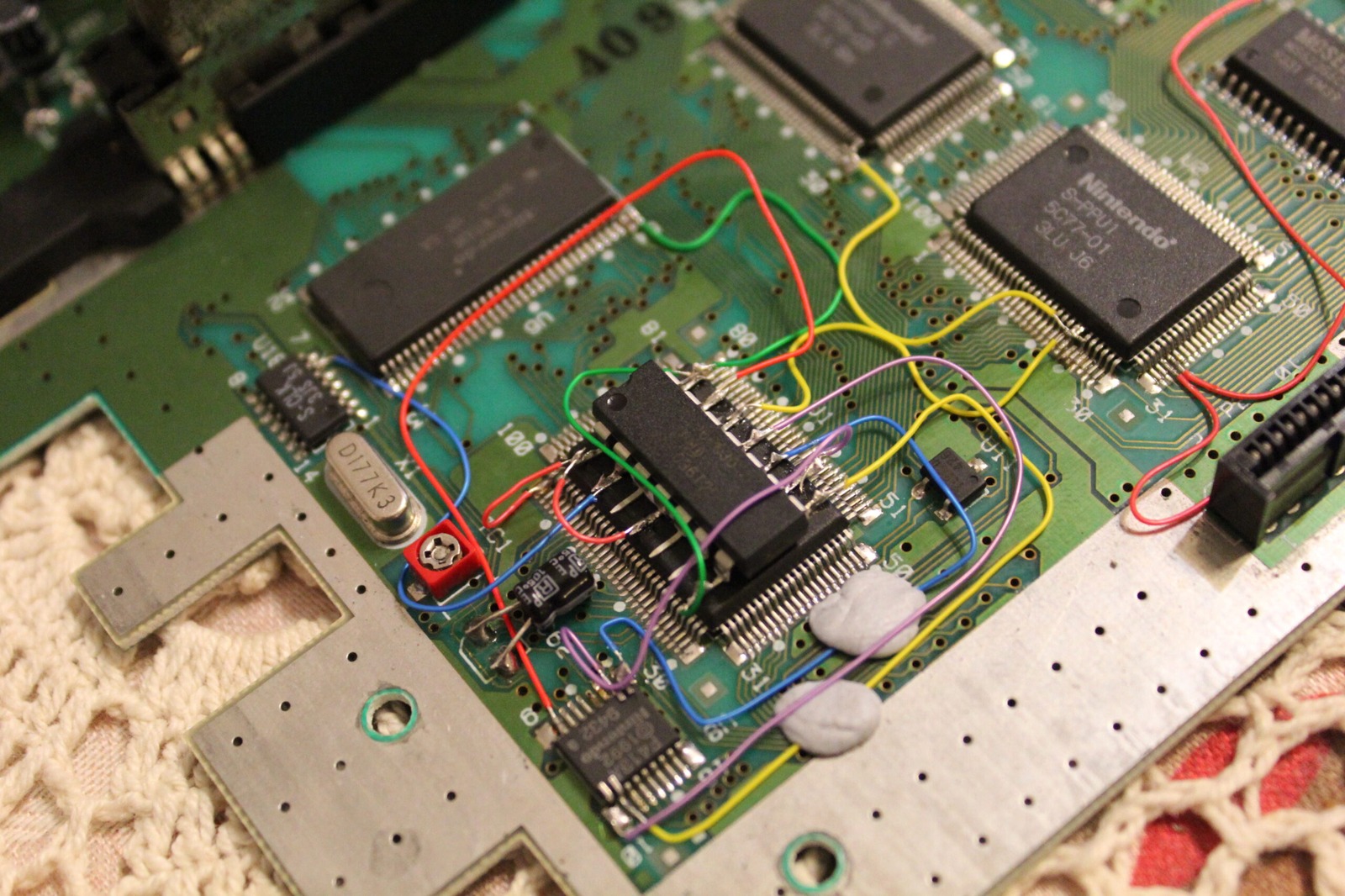
I mounted the PIC16F630 over the CPU. It doesn’t have blast processing so it shouldn’t overheat. ;)
If you are confident your chip has been programmed successfully, consider trimming the legs down. In this example I simply bent them outward slightly. Note the notch on the chip is at the top facing the back of the console.
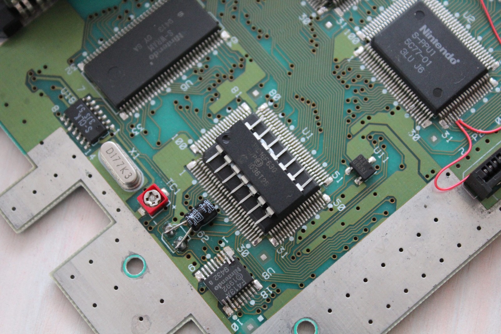
Wiring
Check every connection and check for shorts before powering the console. Use Wolfsoft’s guide and the SuperCIC documentation for the wiring diagram missing from my original article; these photographs record my installation.
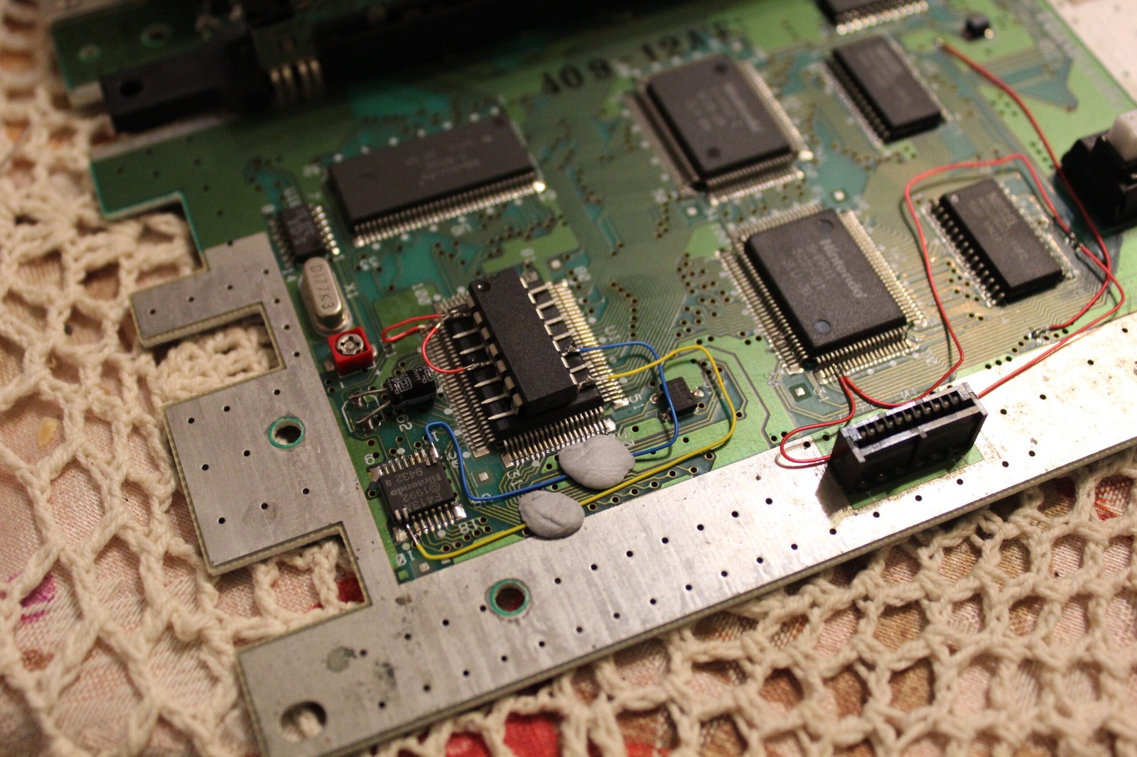
LED
I chose a 5mm red/green dual-colour LED and had 220 ohm resistors on hand, which worked well. The SuperCIC uses the LED to indicate the selected operating mode.
Sources
- SuperCIC - ikari’s project page
- SuperCIC lock firmware source and pin configuration
- Wolfsoft - SuperCIC SNES switchless MOD (PAL)
- LED calculator for single LEDs