 Nix McRetro
The video above is not the one I originally intended to upload. YouTube messed up the upload, then I accidentally deleted the original while trying to recover it. It was gone. Never mind. Enjoy some transformer rantings instead.
Reconnecting the power wiring
These are historical test notes for my two machines. Exposed mains circuitry and stored charge make this work hazardous.
I started the weekend by reconnecting the two blue wires to each other and the two white wires to each other. They had been separated for reasons unknown. I restored them according to their original routing and by comparing the damaged machine with my other CSD-GM1. At this stage I still didn’t know exactly which sections of the machine each rail supplied.
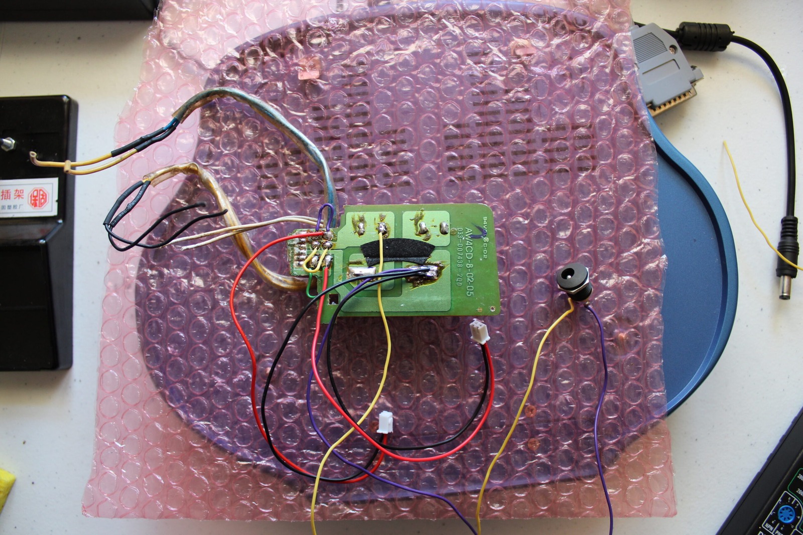
Next came the DC-DC step-down converters. One was initially adjusted to 6.3 V and the other to 9.75 V. Ground was connected to the same point on the battery PCB that feeds into the transformer wiring.
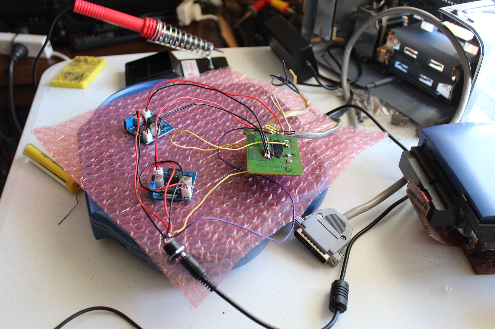
Following the rails
The Mega-CD mechanism connects to the rest of the machine through several harnesses.
In my testing:
- The long connector on the right powers the CD mechanism and front control buttons.
- The medium connector on the left carries an approximately 8 V rail on one pin.
- The short connector on the right provides the supply feeding the Mega Drive section.
That last rail should ultimately produce 5 V for the game hardware, but I was only measuring around 3.3 V and the picture looked terrible.
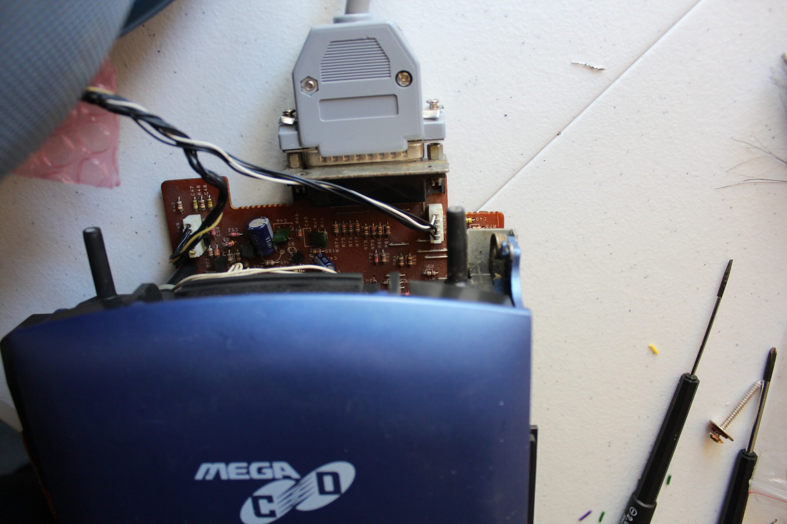
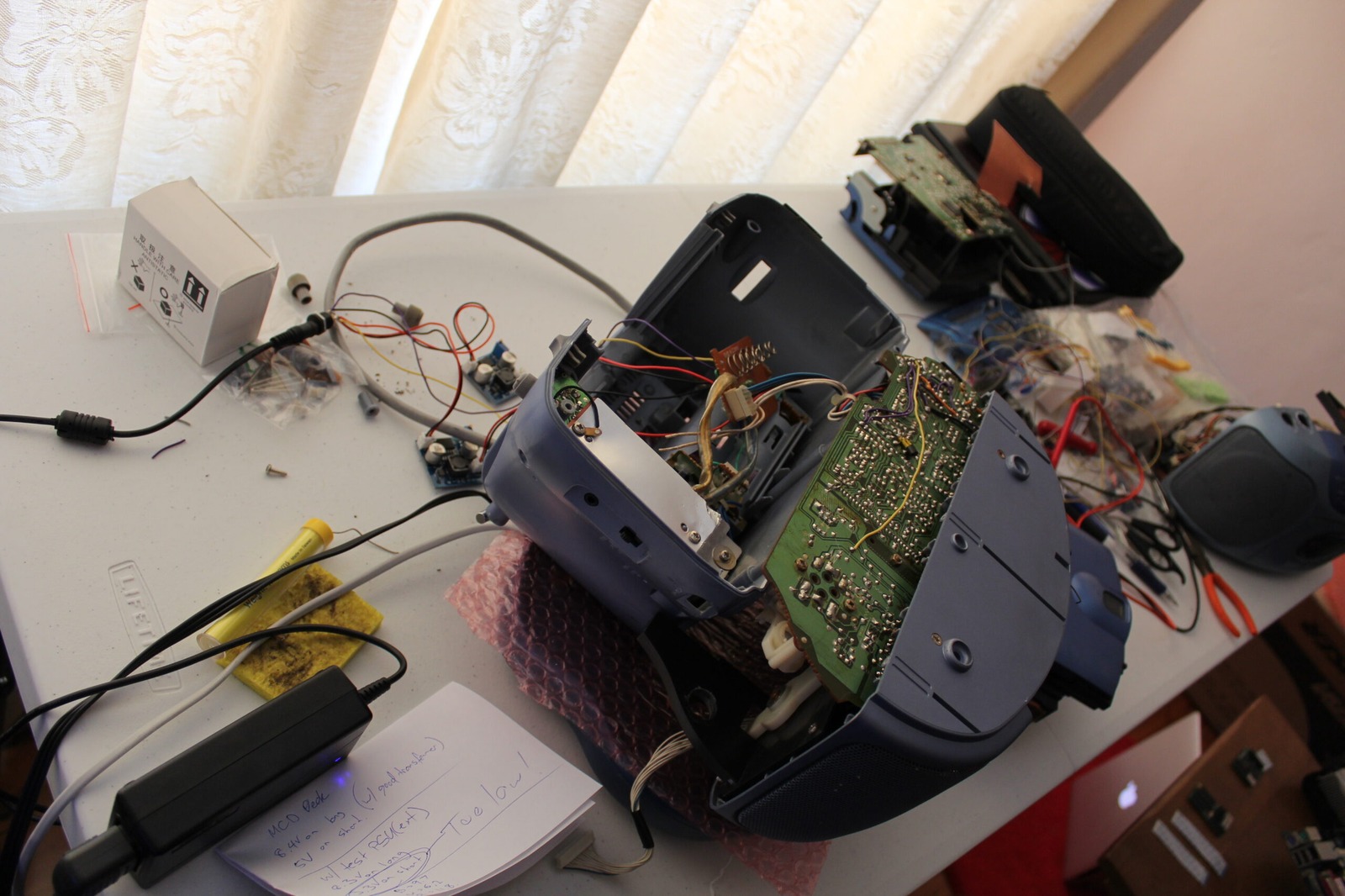
The machine has to sit upside down and backwards for everything to remain connected while testing.
An excellent recipe for sanity.
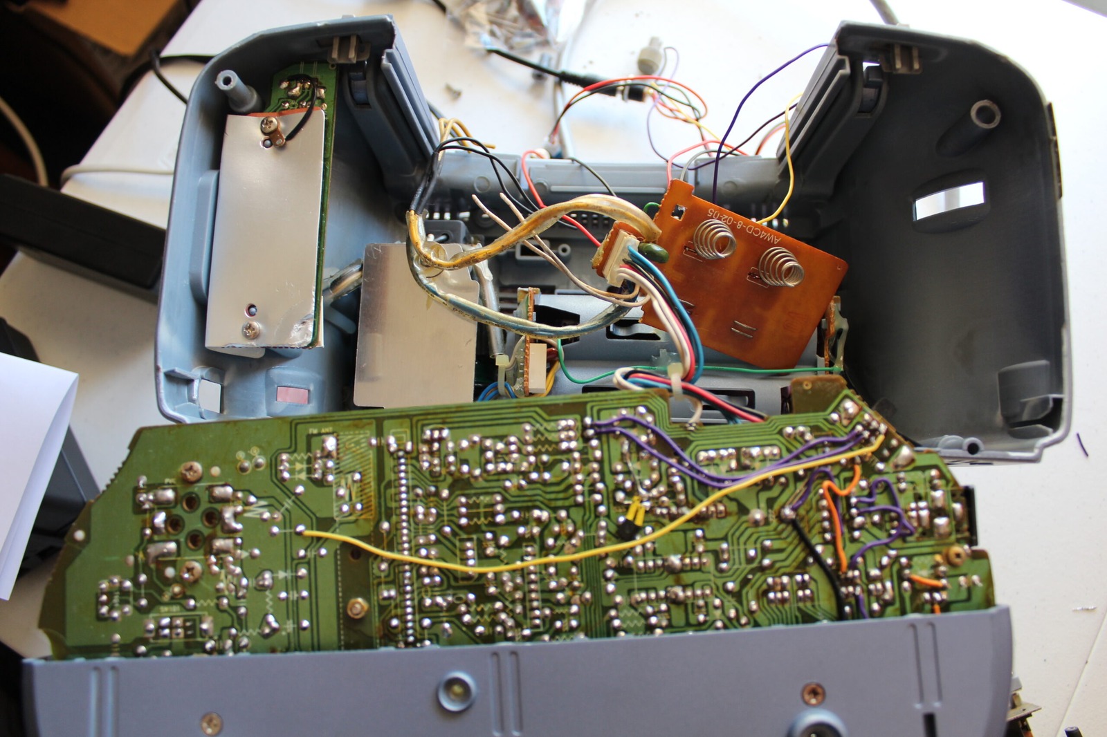
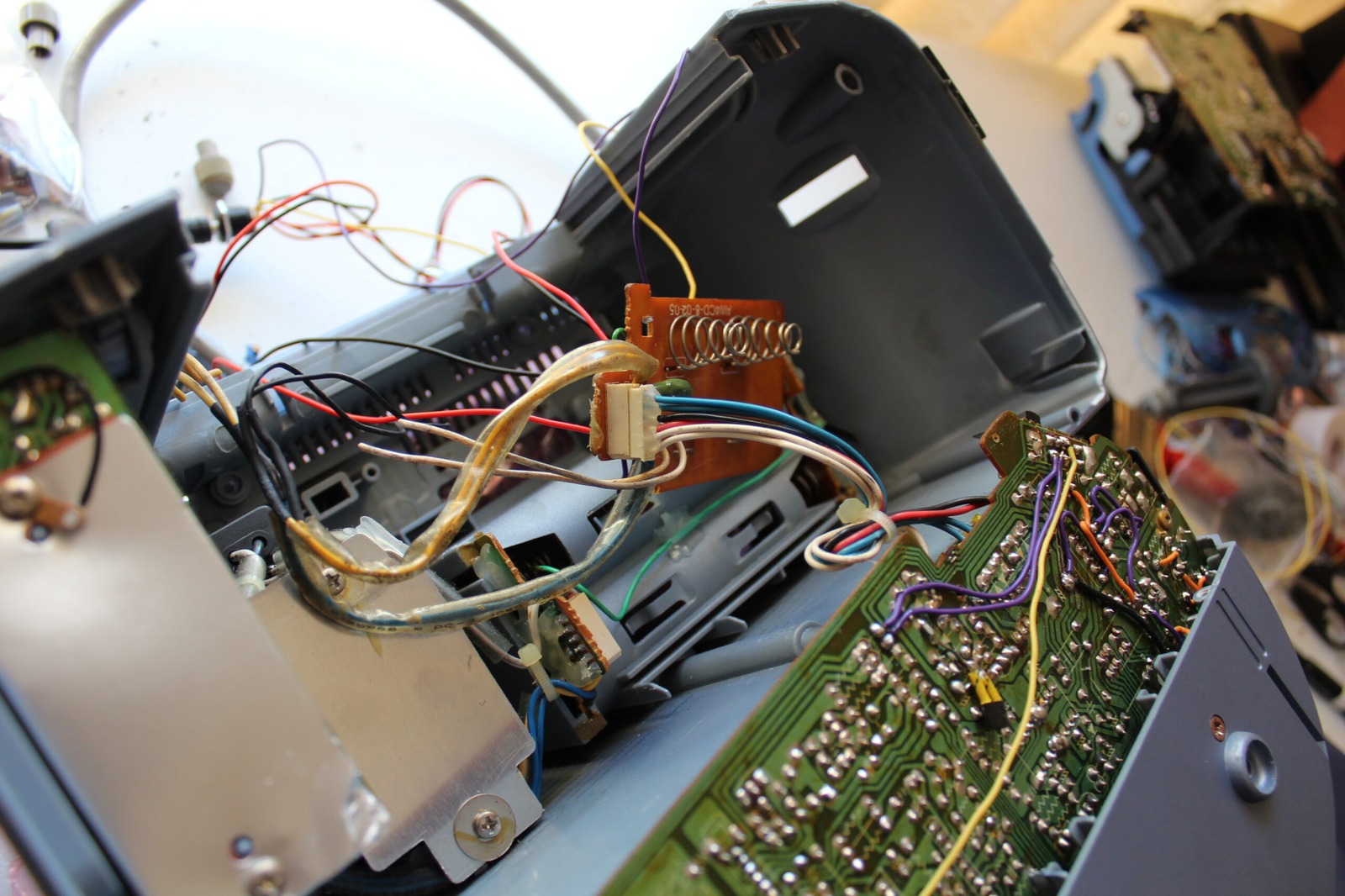
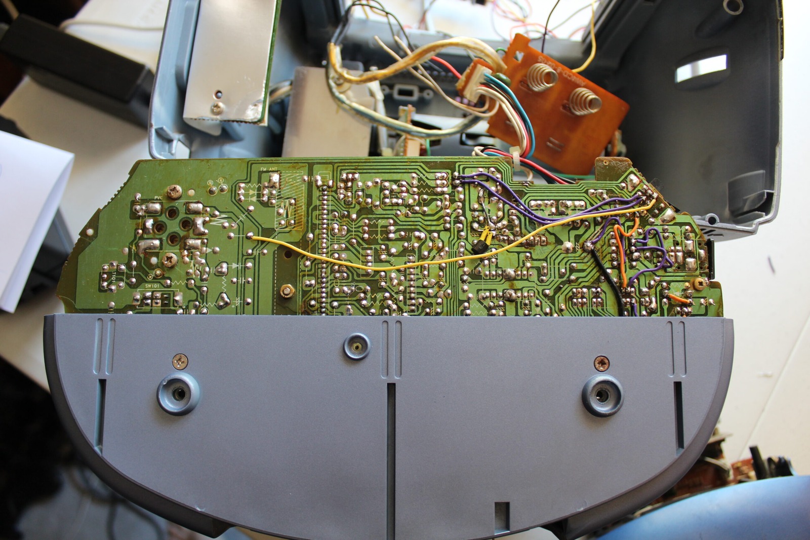
The back of the unit shows the two DC-DC converters connected to power.
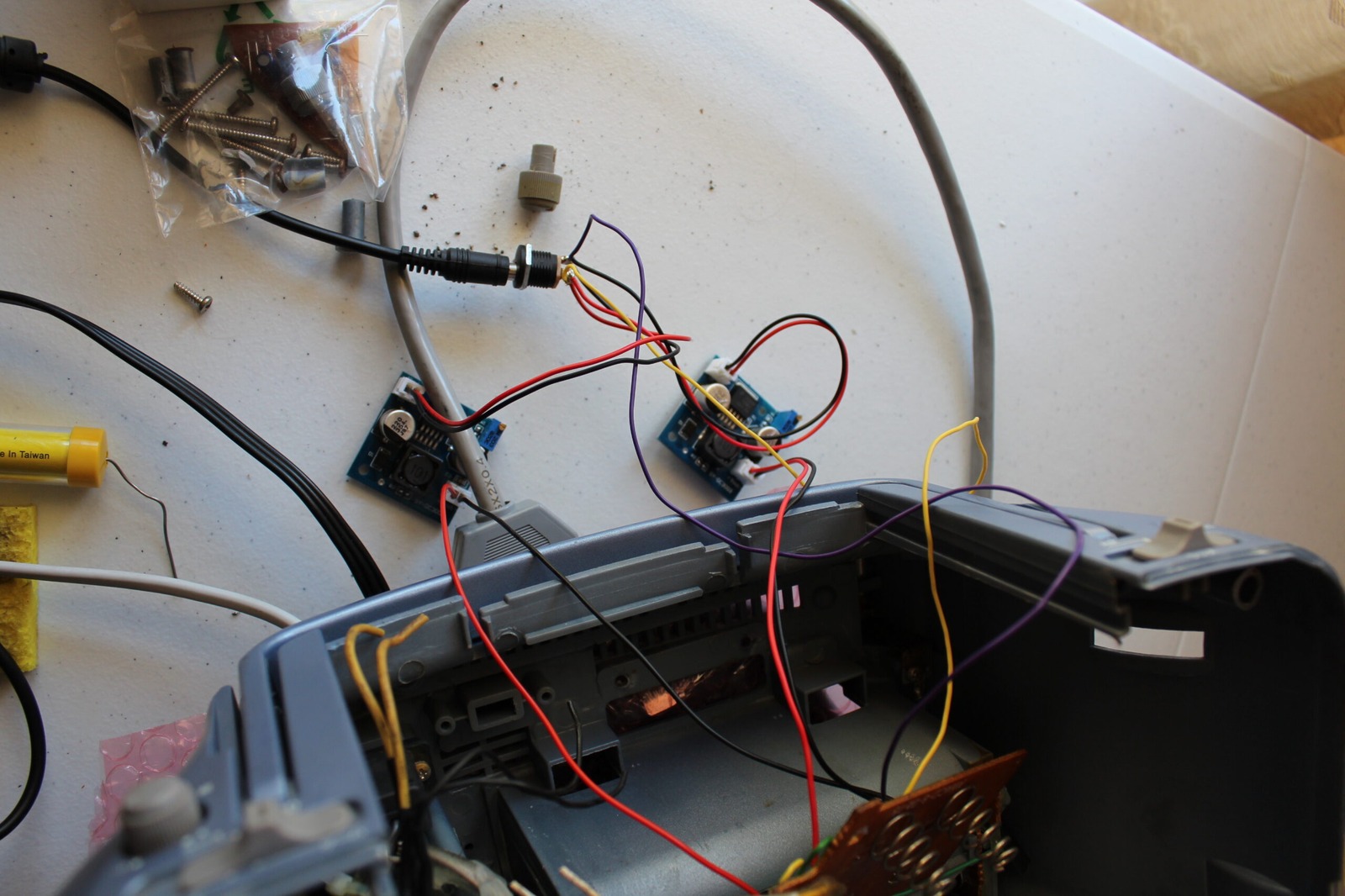
Blue, white, red and black are the colours of the day. I am pretty well acquainted with where they run to on the mainboard now.
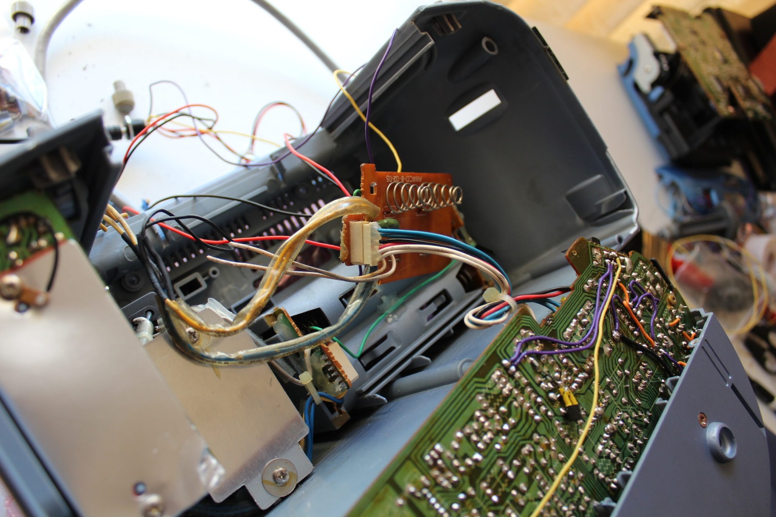
Now to power the unit on and… errr, that’s not looking quite right…
Finding the regulator problem
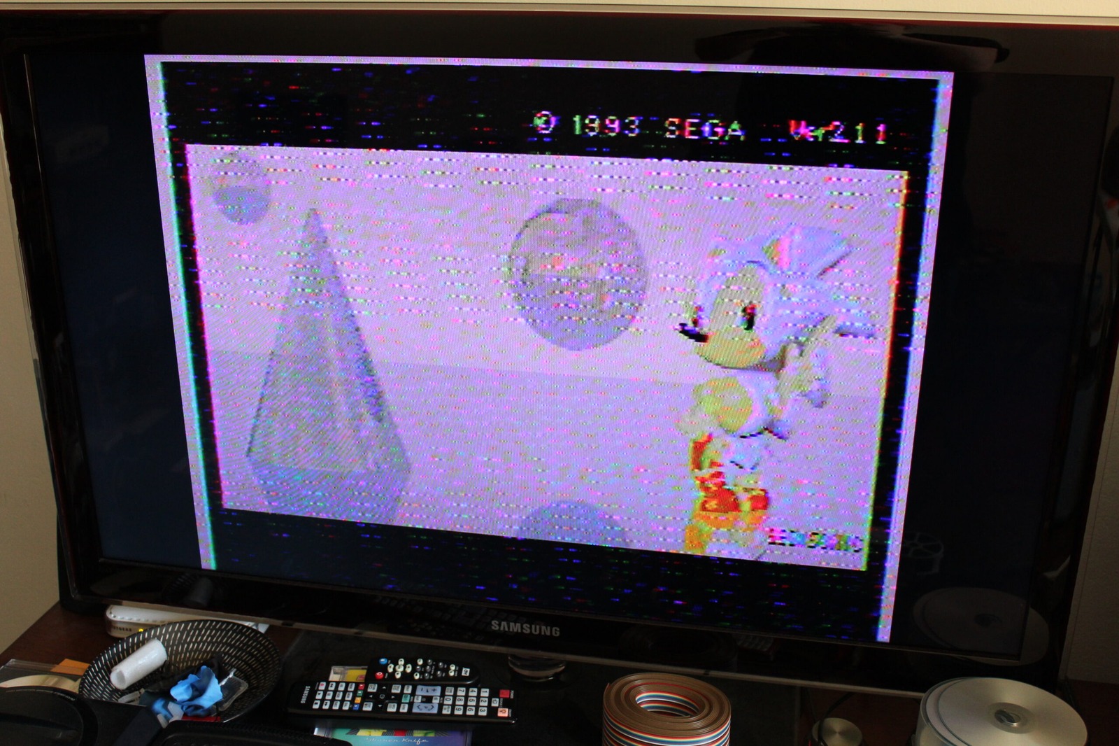
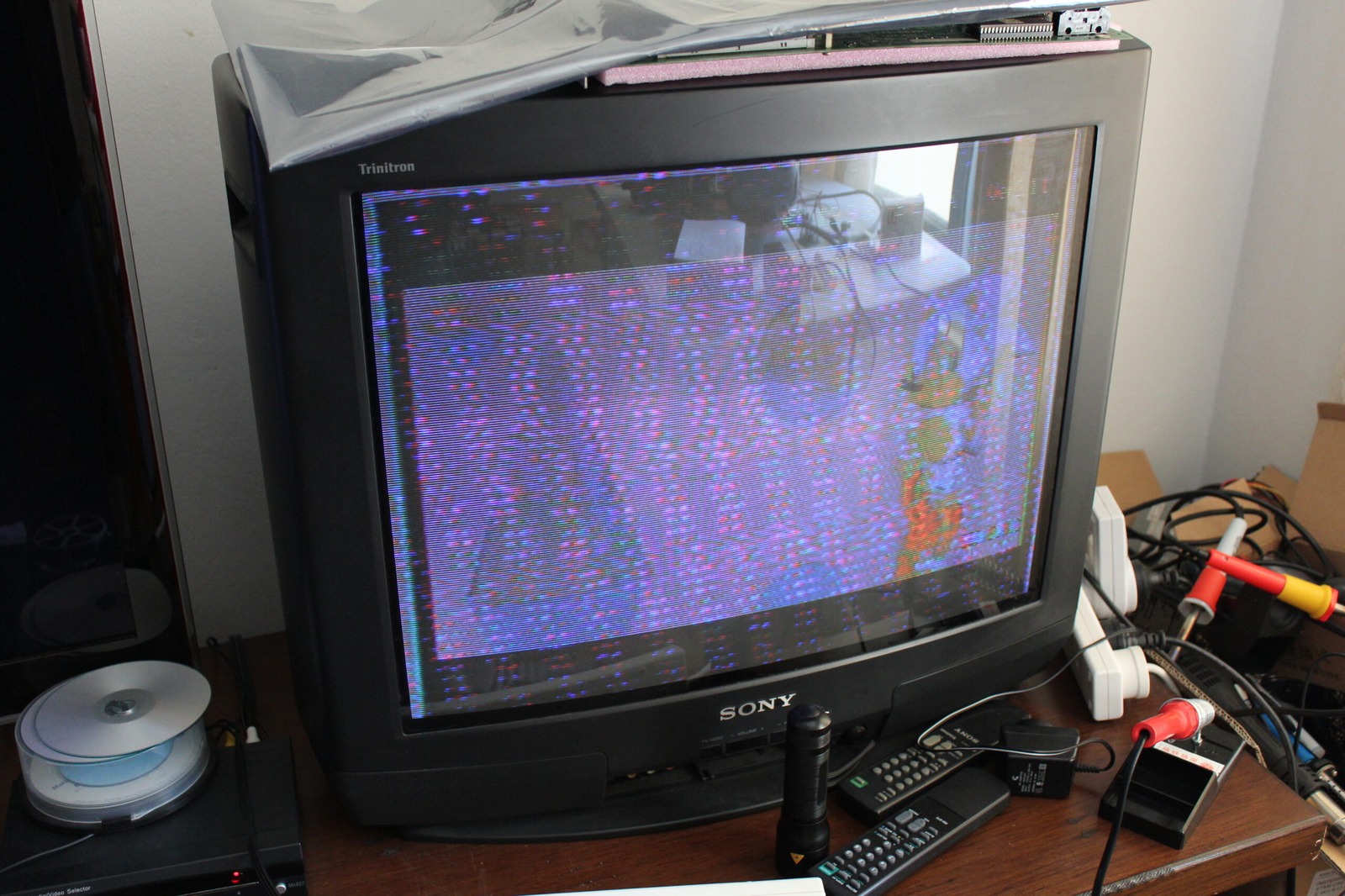
I measured the supplies at several points. One CD-deck rail looked reasonable, while another was almost 2 V too low. More importantly, a regulator that should have been producing around 6 V was only giving me about 4 V.
Disconnecting one converter also established that the white-wire rail was feeding the Mega Drive side. I still did not know exactly what the blue rail powered at this point.
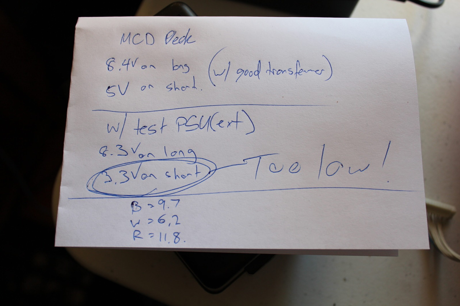
Then the mistake became obvious. I was feeding only 6.3 V into a regulator expected to produce around 6 V. If the regulator behaves like a conventional 7806, that leaves nowhere near enough voltage headroom. A typical 7806 needs roughly another 2 V at its input to regulate properly. So I increased the test input to 8 V.
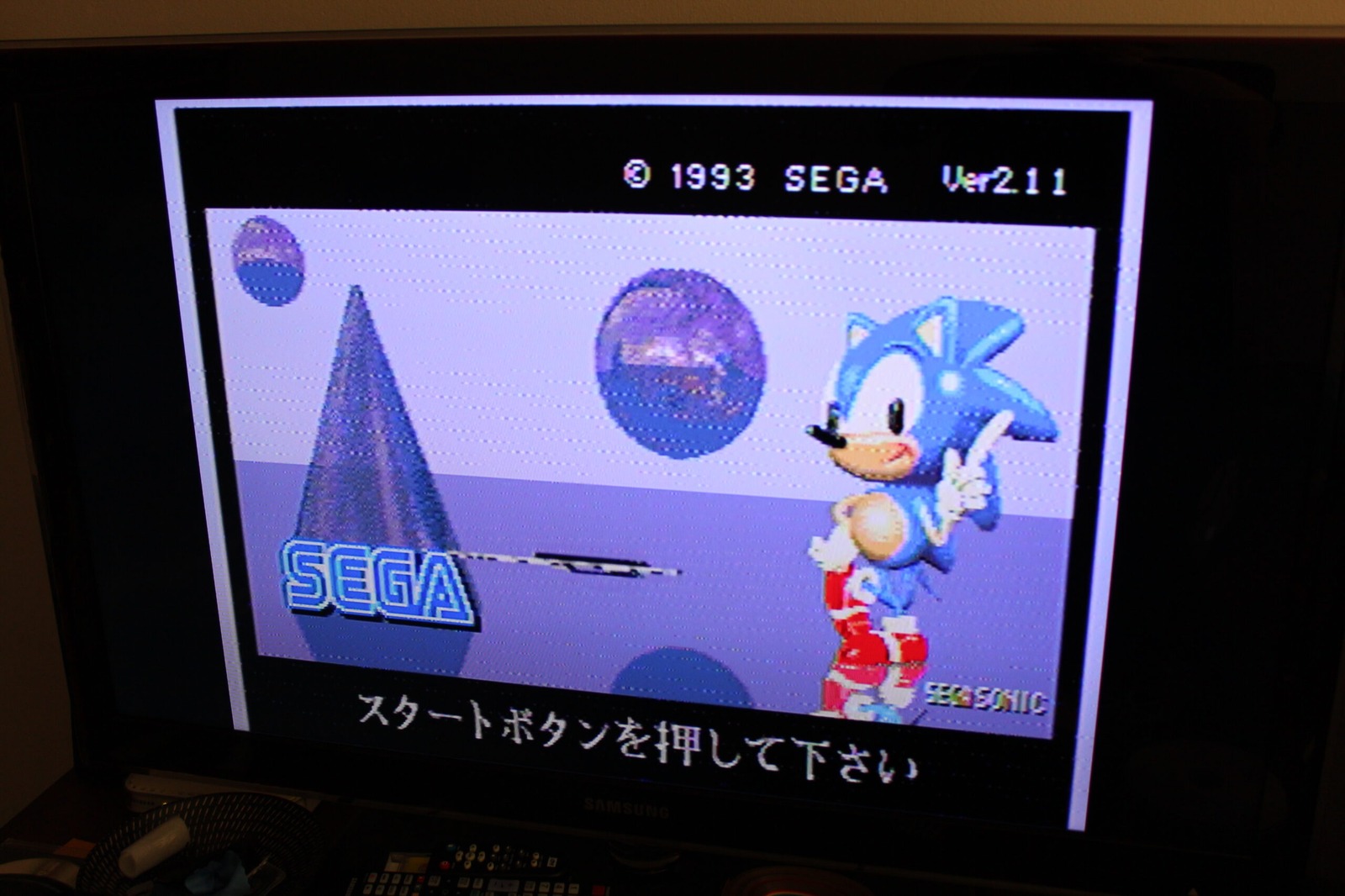
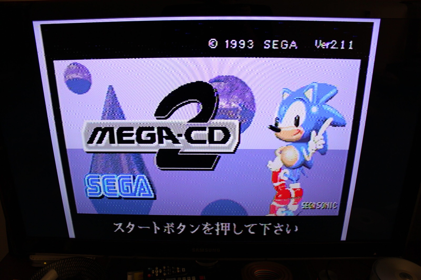
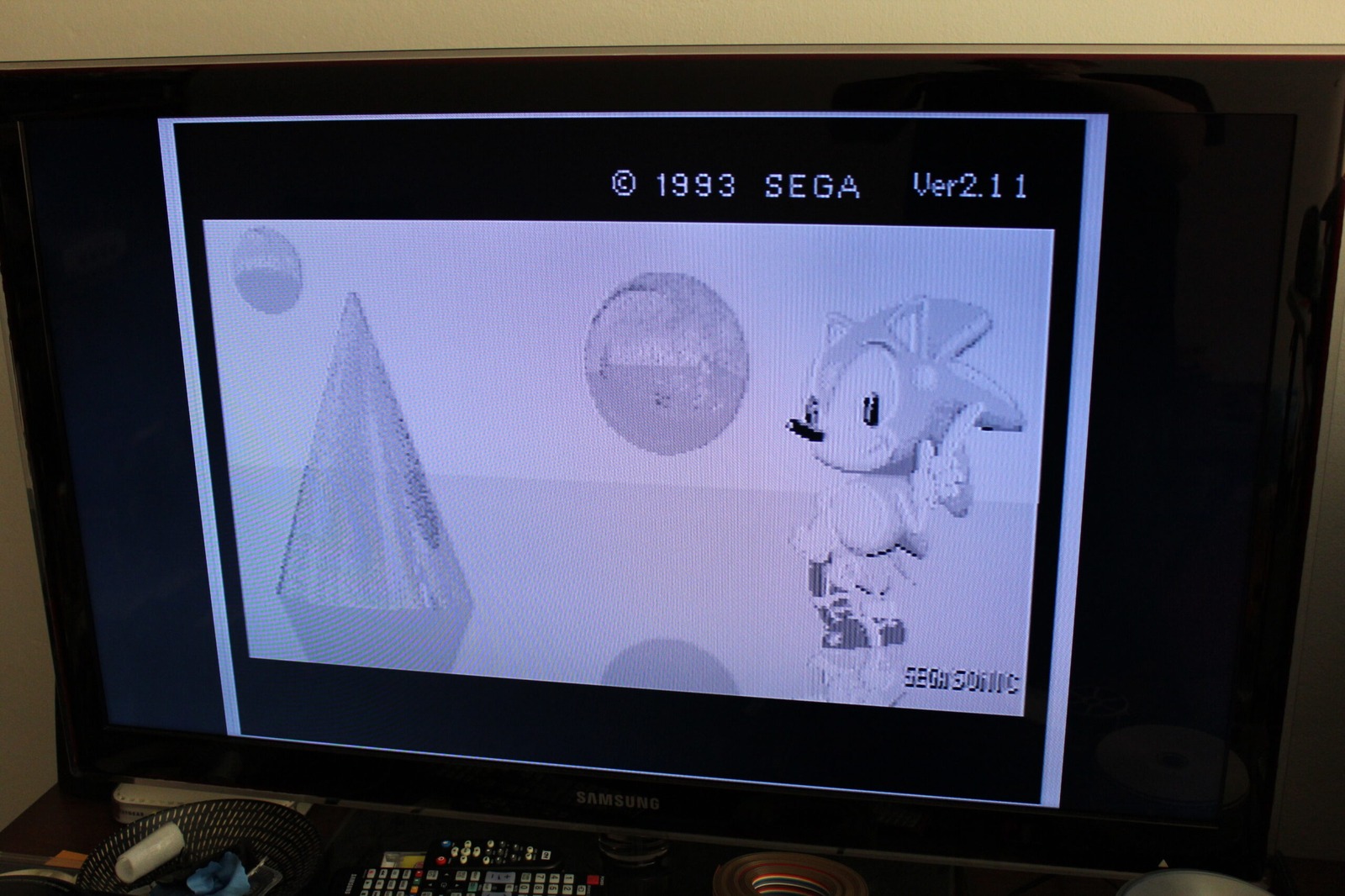
Not only did the picture improve enormously, there was sound from the damaged mainboard as well.
Victory!
More importantly, the result told me something useful. The 6 V rail had been starved of input headroom. It did not prove that the transformer itself was definitely faulty. The transformer, rectification, filter capacitors, wiring and downstream load were all still possibilities that needed to be isolated separately.
What it did show was that my mainboard trace repairs were working well enough for the machine to produce both video and audio. That is a very good result.
I’ve also got the replacement optical pickup for the CD mechanism, so perhaps I’ll even get to play a Mega-CD game on this thing eventually.
Thanks again to Dutchy on the ASSEMblergames forum for reminding me that voltage regulators need some headroom above their regulated output. That may have saved the day.
Related posts
- Aiwa Sega Mega-CD CSD-GM1 Repairs Part 1: Power Restored
- Aiwa Sega Mega-CD CSD-GM1 KSS-210B Laser Replacement
Sources
- STMicroelectronics - L78: Positive voltage regulator ICs - the L7806A electrical-characteristics table gives a typical 2 V dropout at 1 A and 25 °C; actual headroom depends on the part and operating conditions.
- HSE - Electrical safety: Frequently asked questions - explains the hazards of live electrical work and the need to isolate supplies and release stored energy.